
Information


2001 Microchip Technology Inc. DS80067C-page 7
PIC12C67X
4. Module: OSCCAL (Oscillator)
Corrections for the Internal 4 MHz RC Oscillator, Sec-
tion 9.2.5, are shown.
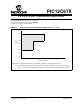
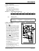
9.2.5 INTERNAL 4 MHz RC OSCILLATOR
OSCCAL, when written to with the calibration
value, will “trim” the internal oscillator to remove
process variation from the oscillator frequency.
Only bits<7:2> of OSCCAL are implemented, and
bits<1:0> should be written as 0 for compatibility
with future devices. The oscillator calibration loca-
tion is not code protected.
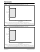
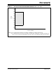
5. Module: Initialization Condition (OSCCAL)
Corrections for Section 9.0, Initialization Conditions for
all registers, Table 9-7, are shown.
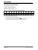
TABLE 9-7: INITIALIZATION CONDITIONS FOR ALL REGISTERS
Engineering Samples for the PIC12C671/2 may or may
not follow this operational clarification for the OSCCAL
register.
Register Power-on Reset MCLR
Resets
WDT Reset
Wake-up via
WDT or Interrupt
OSCCAL 1000 00-- uuuu uu-- uuuu uu--
Legend: u
= unchanged,
x
= unknown,
-
= unimplemented bit, read as ’0’,
q
= value depends on condition.
Note 1: One or more bits in INTCON and PIR1 will be affected (to cause wake-up).
2: When the wake-up is due to an interrupt and the GIE bit is set, the PC is loaded with the interrupt vector (0004h).
3: See Table 9-5 for RESET value for specific condition.
4:
If wake-up was due to A/D completing then bit 6 = 1, all other interrupts generating a wake-up will cause bit 6 =
u
.
5:
If wake-up was due to A/D completing then bit 3 = 0, all other interrupts generating a wake-up will cause bit 3 =
u
.