
User manual


PIC10F200/202/204/206
DS41239A-page 70 Preliminary 2004 Microchip Technology Inc.
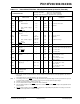
TABLE 12-2: COMPARATOR SPECIFICATIONS
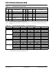
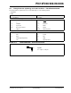
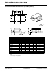
TABLE 12-3: PULL-UP RESISTOR RANGES – PIC10F200/202/204/206
Operating Conditions: 2.0V < VDD <5.5V, -40°C < TA < +125°C, unless otherwise stated.
Param
No.
Sym Characteristics Min Typ Max Units Comments
D300 V
IOFF Input Offset Voltage — ±5.0 TBD mV
D301 V
ICM Input Common Mode Voltage 0 — VDD – 1.5* V
D302 CMRR Common Mode Rejection
Ratio
55* — — db
D303 T
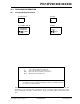
RESP Response Time
(1)
—300 TBD nsVDD = 3.0V to 5.5V, -40° to +85°C
D304 T
MC2OV Comparator Mode Change to
Output Valid
—300 TBD ns
D305 V
IVRF Internal Reference Voltage TBD 0.6 TBD V TBD
Legend: TBD = To Be Determined.
* These parameters are characterized but not tested.
Note 1: Response time measured with one comparator input at (VDD – 1.5)/2 while the other input transitions from VSS
to V
DD.
VDD (Volts) Temperature (°C) Min Typ Max Units
GP0/GP1
2.0 -40 TBD TBD TBD Ω
25 TBD TBD TBD Ω
85 TBD TBD TBD Ω
125 TBD TBD TBD Ω
5.5 -40 TBD TBD TBD Ω
25 TBD TBD TBD Ω
85 TBD TBD TBD Ω
125 TBD TBD TBD Ω
GP3
2.0 -40 TBD TBD TBD Ω
25 TBD TBD TBD Ω
85 TBD TBD TBD Ω
125 TBD TBD TBD Ω
5.5 -40 TBD TBD TBD Ω
25 TBD TBD TBD Ω
85 TBD TBD TBD Ω
125 TBD TBD TBD Ω
Legend: TBD = To Be determined.
* These parameters are characterized but not tested.