
User manual


2004 Microchip Technology Inc. Preliminary DS41239A-page 41
PIC10F200/202/204/206
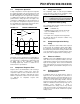
9.0 SPECIAL FEATURES OF THE
CPU
What sets a microcontroller apart from other proces-
sors are special circuits that deal with the needs of real-
time applications. The PIC10F200/202/204/206
microcontrollers have a host of such features intended
to maximize system reliability, minimize cost through
elimination of external components, provide power-
saving operating modes and offer code protection.
These features are:
• Reset:
- Power-on Reset (POR)
- Device Reset Timer (DRT)
- Watchdog Timer (WDT)
- Wake-up from Sleep on pin change
- Wake-up from Sleep on comparator change
• Sleep
• Code Protection
• ID Locations
• In-Circuit Serial Programming™
•Clock Out
The PIC10F200/202/204/206 devices have a Watch-
dog Timer, which can be shut off only through configu-
ration bit WDTE. It runs off of its own RC oscillator for
added reliability. When using INTRC, there is an 18 ms
delay only on V
DD power-up. With this timer on-chip,
most applications need no external Reset circuitry.
The Sleep mode is designed to offer a very low current
Power-down mode. The user can wake-up from Sleep
through a change on input pins, wake-up from
comparator change, or through a Watchdog Timer
time-out.
9.1 Configuration Bits
The PIC10F200/202/204/206 Configuration Words
consist of 12 bits. Configuration bits can be
programmed to select various device configurations.
One bit is the Watchdog Timer enable bit, one bit is the
MCLR
enable bit and one bit is for code protection (see
Register 9-1).
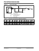
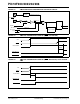
REGISTER 9-1: CONFIGURATION WORD FOR PIC10F200/202/204/206
(1, 2)
— — — — — — — MCLRE CP WDTE — —
bit 11 bit 0
bit 11-5 Unimplemented: Read as ‘0’
bit 4 MCLRE: GP3/MCLR Pin Function Select bit
1 = GP3/MCLR pin function is MCLR
0 = GP3/MCLR pin function is digital I/O, MCLR internally tied to VDD
bit 3 CP: Code Protection bit
1 = Code protection off
0 = Code protection on
bit 2 WDTE: Watchdog Timer Enable bit
1 = WDT enabled
0 = WDT disabled
bit 1-0 Reserved: Read as ‘0’
Note 1: Refer to the “PIC10F200/202/204/206 Memory Programming Specifications” (DS41228) to
determine how to access the Configuration Word. The Configuration Word is not user
addressable during device operation.
2: INTRC is the only oscillator mode offered on the PIC10F200/202/204/206.
Legend:
R = Readable bit W = Writable bit U = Unimplemented bit, read as ‘0’
-n = Value at POR ‘1’ = bit is set ‘0’ = bit is cleared x = bit is unknown