
Datasheet


7
Atmel MSL3086/MSL3088 Datasheet
8-String 60mA LED Drivers with Integrated Boost Controller and Phase Shifted Dimming
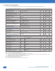
5.0 Typical Operating Characteristics
(Typical Operating Circuit, unless otherwise stated, TA = +25°C, unless otherwise noted)
MSL3086/MSL3087/MSL3088 Datasheet
Page 6 of 26
© Atmel Inc., 2011. All rights reserved.
Note 3. t
VD:DAT
= minimum SDA output data-valid time following SCL LOW transition.
Note 4. A master device must internally provide an SDA hold time of at least 300ns to ensure an SCL low state.
Note 5. The maximum SDA and SCL rise times is 300ns. The maximum SDA fall time is 250ns. This allows series protection resistors
to be connected between SDA and SCL inputs and the SDA/SCL bus lines without exceeding the maximum allowable rise
time.
Note 6. MSL3086/87/88 include input filters on SDA and SCL that suppress input noise less than 50ns
Note 7. Parameter is guaranteed by design and not production tested.
Note 8. Per JEDEC specification JESD51-5 and JESD51-12.
Note 9. Tests performed at T
A
= 25°C, specifications over temperature guaranteed by design.
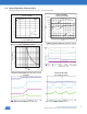
Typical Operating Characteristics
(Typical Application Circuit, unless otherwise stated)
BOOST REGULATOR EFFICIENCY vs.
OUTPUT CURRENT
0
10
20
30
40
50
60
70
80
90
100
0 200 400 600 800 1,000
OUTPUT CURRENT (mA)
EFFICIENCY (%
)
V
PWR
= 12V
V
LED
37V
f
BOOST
= 625kHz
SUPPLY CURRENT
vs. SUPPLY VOLTAGE
0.01
0.1
1
10
100
1000
10000
4.5 4.6 4.7 4.8 4.9 5.0 5.1 5.2 5.3 5.4 5.5
V
IN
(V)
I
IN
(µA)
EN = 0
EN = 1
sleep = slpPwrSv = 1
EN = 1
sleep = slpPwrSv = 0
BOOST NOT SW ITCHING
POWER-UP WAVEFORMS INTO 100% DUTY CYCLE
STR
n
CURRENT vs. R
ISET
0
5
10
15
20
25
30
35
40
45
50
55
60
65
70
75
10 100 1000
R
ISET
(k
)
STRn CURRENT (m
A
CH1 = V
EN
, CH2 = V
LED
, CH3 = V
STRx
, CH4 = I
PWR
MSL3086/MSL3087/MSL3088 Datasheet
Page 7 of 26
© Atmel Inc., 2011. All rights reserved.
POWER-UP WAVEFORMS INTO 100% DUTY CYCLE
(ZOOM IN)
CH1 = V
EN
, CH2 = V
LED
, CH3 = V
STRx
, CH4 = I
PWR
AUTO CALIBRATION
CH2 = V
LED
, CH3 = V
STRx
BOOST WAVEFORMS
10% LED DUTY CYCLE
CH1 = V
LED
, CH2 = V
GATE
, CH3 = I
INDUCTOR
BOOST WAVEFORMS
100% LED DUTY CYCLE
CH1 = V
LED
, CH2 = V
GATE
, CH3 = I
INDUCTOR
0.01
0.1
1
10
100
1000
10000
100000
1000000
4.5 4.6 4.7 4.8 4.9 5.0 5.1 5.2 5.3 5.4 5.5
I
IN
(µA)
V
IN
(V)
SUPPLY CURRENT
vs. SUPPLY VOLTAGE
EN = 0
EN = 1
sleep = slpPwrSv = 1
EN = 1
sleep = slpPwrSv = 0
BOOST NOT SWITCHING