
Datasheet


9Atmel LED Drivers-MSL1061/MSL1064
PIN NAME MSL1061 MSL1064 PIN DESCRIPTION
IADJ 13 11
Analog LED current dimming input
Apply a voltage between 0V to 1.22V to linearly control the LED current from 0 to 100%.
Connect IADJ to VDD if unused
STR5 14 12
LED string 5 current sink output
Connect the cathode of LED String 5 to STR5. Connect STR5 to GND if unused
STR4 15 13
LED string 4 current sink output
Connect the cathode of LED String 4 to STR4. Connect STR4 to GND if unused
STR3 16 14
LED string 3 current sink output
Connect the cathode of LED String 3 to STR3. Connect STR3 to GND if unused
STR2 17 15
LED string 2 current sink output
Connect the cathode of LED String 2 to STR2. Connect STR2 to GND if unused
STR1 18 16
LED string 1 current sink output
Connect the cathode of LED String 1 to STR1. Connect STR1 to GND if unused
STR0 19 17
LED string 0 current sink output
Connect the cathode of LED String 0 to STR0. Connect STR0 to GND if unused
OVP 21 18
Overvoltage detection input
Connect a resistive voltage divider from the boost output voltage to OVP to set the
overvoltage protection set point. OVP threshold is 1.28V
N/C 22 19 No internal connection. Leave unconnected
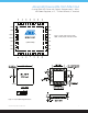
SW
23, 24, 25,
26
20, 21
Drain of the internal boost power MOSFET switch
Connect all SW pins together and to the boost regulator inductor and rectier
N/C - 22 No internal connection. Leave unconnected
EN 27 23
Enable input (active high)
Drive EN high to turn on the MSL1061/64, and drive it low to turn it off.
For automatic startup, connect EN to VIN through a 100kΩ resistor
VIN 28 24
Supply voltage input
Connect the input supply voltage to VIN.
VIN powers the internal linear regulator that powers VCC.
Bypass VIN to GND with a 1µF or greater ceramic capacitor
GND
Exposed
pad
Exposed
pad
Ground
Atmel LED Drivers-MSL1061/MSL1064
6-string PWM LED Driver with Digitally Compensated, 1.1MHz,
48V Boost Regulator, ±1.5% Current Balance, I
2
C Interface