
Datasheet


8 Atmel LED Drivers-MSL1061/MSL1064
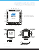
PIN NAME MSL1061 MSL1064 PIN DESCRIPTION
VCC 1 1
6V internal linear regulator output
VCC powers the internal power FET switch driver.
Bypass VCC to GND either with a 10µF or greater ceramic capacitor, or with a 10µF or
greater tantalum capacitor in parallel with a 1µF ceramic capacitor.
If the voltage at VIN is less than 6.5V, connect VCC directly to VIN to bypass the internal
linear regulator, and power the driver directly from VIN
VDD 2 2
2.9V internal linear regulator output
VDD powers internal logic. Bypass VDD to GND with at least a 4.7µF ceramic capacitor
TEST1 3 3 Factory test connection. Leave unconnected
TEST2 4 4 Factory test connection. Connect to GND
SDA 5 5
I²C serial data I/O
SDA is the data I/O for the I²C serial interface
SCL 6 6
I²C serial clock input
SCL is the clock input for the I²C serial interface
AD0 7 -
I²C slave ID selection input
For MSL1061, connect AD0 to GND, VDD, SCL, or SDA to set the I²C slave ID to 0x60,
0x61, 0x62, or 0x63. The MSL1064 I²C slave ID is xed at 0x62, and is not user-selectable
PWM 8 7
PWM control input
Drive PWM with a PWM signal up to 40kHz to pulse-width-modulate the LED current
FLTB 9 8
Fault indication output (active low)
FLTB sinks current to GND whenever the MSL1061/64 detects a fault.
Once a fault is detected, FLTB remains low until EN is toggled low/high, input power is
cycled off/on, or the fault status is reset through the I²C interface.
OSC 10 9
Oscillator control input
Connect a 115kΩ, 1% resistor from OSC to GND to set the internal oscillator frequency
to 11MHz and the boost regulator switching frequency to 1.1MHz
TEST3 11 - Factory test connection with internal 1.8kΩ pull-up to VDD. Leave unconnected
ILED 12 10
Maximum LED current control input
Connect a resistor from ILED to GND to set the full-scale LED string current.
For example, connect a 100kΩ resistor to GND to set a 20mA sink current through
each LED string
Pin Descriptions
Table 3. Pin Assignments