
User's Manual
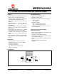
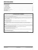
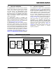
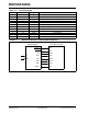
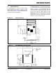
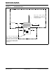
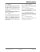
Table Of Contents
- Features
- Operational
- RF/Analog Features
- Media Access Controller (MAC)/ Baseband Features
- Pin diagram
- Table of Contents
- Most Current Data Sheet
- Errata
- Customer Notification System
- 1.0 Device Overview
- 2.0 Circuit Description
- 3.0 Regulatory Approval
- 4.0 Electrical Characteristics
- Appendix A: Revision History
- Product Identification System
- Corporate Office
- Atlanta
- Boston
- Chicago
- Cleveland
- Fax: 216-447-0643
- Dallas
- Detroit
- Indianapolis
- Toronto
- Fax: 852-2401-3431
- Australia - Sydney
- China - Beijing
- China - Shanghai
- India - Bangalore
- Korea - Daegu
- Korea - Seoul
- Singapore
- Taiwan - Taipei
- Fax: 43-7242-2244-393
- Denmark - Copenhagen
- France - Paris
- Germany - Munich
- Italy - Milan
- Spain - Madrid
- UK - Wokingham
- Worldwide Sales and Service

MRF89XAM9A
DS00000A-page 6 Preliminary © 2011 Microchip Technology Inc.
FIGURE 1-5: MOUNTING DETAILS
3.4”
3.4”
0.4”
0.4”
Edge of PCB
0.470”
Keep area around antenna
(approximately 3.4 (6.8 cm)
inches) clear of metallic structures
for best performance
Host PCB Top Copper Ground
Plane (Antenna Counterpoise):
Extend the host PCB top copper
ground plane under and to the left
and right side of the module at least
0.4 inches (1 cm) for best antenna
performance.