
User's Manual
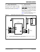
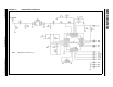
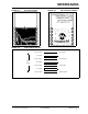
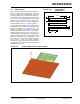
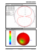
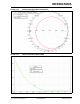
Table Of Contents
- Features
- Operational
- RF/Analog Features
- Media Access Controller (MAC)/ Baseband Features
- Pin diagram
- Table of Contents
- Most Current Data Sheet
- Errata
- Customer Notification System
- 1.0 Device Overview
- 2.0 Circuit Description
- 3.0 Regulatory Approval
- 4.0 Electrical Characteristics
- Appendix A: Revision History
- Product Identification System
- Corporate Office
- Atlanta
- Boston
- Chicago
- Cleveland
- Fax: 216-447-0643
- Dallas
- Detroit
- Indianapolis
- Toronto
- Fax: 852-2401-3431
- Australia - Sydney
- China - Beijing
- China - Shanghai
- India - Bangalore
- Korea - Daegu
- Korea - Seoul
- Singapore
- Taiwan - Taipei
- Fax: 43-7242-2244-393
- Denmark - Copenhagen
- France - Paris
- Germany - Munich
- Italy - Milan
- Spain - Madrid
- UK - Wokingham
- Worldwide Sales and Service

© 2011 Microchip Technology Inc. Preliminary DS00000A-page 14
MRF89XAM9A
2.3 PCB Antenna
The PCB antenna is fabricated on the top copper trace.
Figure 2-11 shows the trace dimensions. The layers
below the antenna have no copper traces. The ground
and power planes under the components serve as a
counterpoise to the PCB antenna. Additional ground
plane on the host PCB will substantially enhance the
performance of the module. For best performance,
place the module on the host PCB by following the
recommendations in Section 1.2, Mounting Details.
The PCB antenna was designed and simulated using
Ansoft Designer
®
and HFSS™ 3D full-wave solver
software by ANSYS, Inc. (www.ansoft.com). The
design goal was to create a compact, low-cost antenna
with the best radiation pattern. Figure 2-11 shows the
simulation drawing and Figure 2-12 and Figure 2-13
show the 2D and 3D radiation patterns, respectively. As
shown by the radiation patterns, the performance of the
antenna is dependant upon the orientation of the
module. Figure 2-14 shows the impedance simulation
and Figure 2-15 shows the actual impedance
measurement. The discrete matching circuitry matches
the impedance of the antenna with the SAW filter and
MRF89XA transceiver IC.
FIGURE 2-10: PCB ANTENNA
DIMENSIONS
FIGURE 2-11: PCB ANTENNA SIMULATION DRAWING
16.8mm
1.0mm
8.4mm
1.1mm
0.5mm
2.5mm