
User's Manual
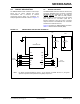
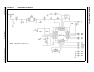
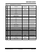
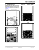
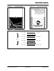
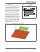
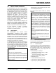
Table Of Contents
- Features
- Operational
- RF/Analog Features
- Media Access Controller (MAC)/ Baseband Features
- Pin diagram
- Table of Contents
- Most Current Data Sheet
- Errata
- Customer Notification System
- 1.0 Device Overview
- 2.0 Circuit Description
- 3.0 Regulatory Approval
- 4.0 Electrical Characteristics
- Appendix A: Revision History
- Product Identification System
- Corporate Office
- Atlanta
- Boston
- Chicago
- Cleveland
- Fax: 216-447-0643
- Dallas
- Detroit
- Indianapolis
- Toronto
- Fax: 852-2401-3431
- Australia - Sydney
- China - Beijing
- China - Shanghai
- India - Bangalore
- Korea - Daegu
- Korea - Seoul
- Singapore
- Taiwan - Taipei
- Fax: 43-7242-2244-393
- Denmark - Copenhagen
- France - Paris
- Germany - Munich
- Italy - Milan
- Spain - Madrid
- UK - Wokingham
- Worldwide Sales and Service

© 2011 Microchip Technology Inc. Preliminary DS00000A-page 9
MRF89XAM9A
2.0 CIRCUIT DESCRIPTION
The MRF89XAM9A module interfaces to Microchip’s
PIC16, PIC 18, PIC24, dsPIC33 and PIC32
microcontrollers with a minimum of external
components through digital only connections. An
example application schematic is shown in Figure 2-2.
2.1 Module Schematic
The MRF89XAM9A module is based on the Microchip
Technology MRF89XA Ultra Low-Power, Integrated
ISM Band sub-GHz Transceiver IC. The serial I/O
(CSCON
, CSDATA, SCK, SDO and SDI), RESET,
IRQ0 and IRQ1 pins are brought out to the module
pins. Crystal X1 is a 12.8 MHz crystal with a
frequency tolerance of ±10 ppm at 25°C. The RFIO
output is matched to the SAW filter FL1 and further
matched to the PCB trace antenna.
Figure 2-2 illustrates the MRF89XAM9A schematics.
Table 2-1 details the Bill of Materials (BOM).
FIGURE 2-1: MRF89XAM9A APPLICATION SCHEMATIC
Note 1
+
C2
1 0
μ
F
C1
0.1
μ
F
To Host
Microcontroller
To Host
Microcontroller
U1
MRF89XAM9A-I/RM
+ 3.3V
GND
RESET
CSCON
IRQ0
SDI
SCK
GND
GND
V
IN
IRQ1
CSDATA
SDO
1
2
3
4
5
6
12
11
10
9
8
7
Note: For battery powered applications, place a 10 μF capacitor in parallel with the 0.1 μF bypass
capacitor to provide a low impedance during startup sequences.