
User manual


MRF89XAMxA PICtail™/PICtail Plus Daughter Board User’s Guide
DS70653A-page 10 © 2011 Microchip Technology Inc.
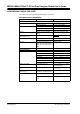
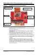
FIGURE 1-1: MRF89XAMXA PICtail™/PICtail PLUS DAUGHTER BOARD
PICtail Plus Connector (P1) – 30-pin card edge connector for connecting to the16-bit
and 32-bit development boards’ PICtail Plus connector.
PICtail Connector (P2) – 28-pin right angle connector to connect to the 8-bit develop-
ment boards’ PICtail connector.
MRF89XAM8A (U1) – Ultra Low-Power Sub-GHz transceiver module – 868 MHz.
MRF89XAM9A (U1) – Ultra Low-Power Sub-GHz transceiver module – 915 MHz.
Power Disconnect/Current Measure Jumpers (JP1/JP2) – Two 2-pin headers are
connected in parallel. A shunt on one of the two headers connects power to the
MRF89XAMxA module. A current meter can be placed on the open header and when
the shunt is removed from the opposite header, current consumption can be measured
without interrupting power. A useful cable that can be connected to the 2-pin header
and current meter, using banana plugs, is the XLP Current Measurement Cable
(AC002023).
INT2 Jumper (JP3) – Jumpering JP3 with a shunt allows you to connect RA5 to
RB2/INT2, this enables push button switch S2 to trigger an interrupt. For more
information, see
Section 2.2.1 “Configuring Push Button Switch S2 to RB2/INT2”.
EUI Node Identity Serial EEPROM (U3) – Contains a unique IEEE EUI address. For
more information, refer to the “2K SPI Bus Serial EEPROM with EUI-48™ Node Iden
-
tity Data Sheet” (DS22123).
MRF89XAM8A or
MRF89XAM9A Module
Power Disconnect/Current
Measure Jumpers
INT2 Jumper
PICtail™ and PICtail
Plus Connectors
25AA02E48 EUI
Node Identity
Serial EEPROM