
Datasheet


MCP7940N
DS20005010F-page 32 2010-2014 Microchip Technology Inc.
5.7 Battery Backup
The MCP7940N features a backup power supply input
(V
BAT) that can be used to provide power to the time-
keeping circuitry, RTCC registers, and SRAM while pri-
mary power is unavailable. The MCP7940N will
automatically switch to backup power when V
CC falls
below V
TRIP, and back to VCC when it is above VTRIP.
The VBATEN bit must be set to enable the V
BAT input.
The following functionality is maintained while operat-
ing on backup power:
• Timekeeping
•Alarms
• Alarm Output
• Digital Trimming
• RTCC Register and SRAM Contents
The following features are not available while operating
on backup power:
•I
2
C Communication
• Square Wave Clock Output
• General Purpose Output
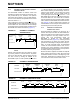
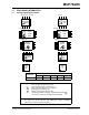
5.7.1 POWER-FAIL TIME-STAMP
The MCP7940N includes a power-fail time-stamp mod-
ule that stores the minutes, hours, date, and month
when primary power is lost and when it is restored
(Figure 5-8). The PWRFAIL bit is also set to indicate
that a power failure occurred.
To utilize the power-fail time-stamp feature, a backup
power supply must be available with the V
BAT input
enabled, and the oscillator should also be running to
ensure accurate functionality.
FIGURE 5-8: POWER-FAIL TIME-STAMP TIMING
Note: Throughout this section, references to the
register and bit names for the Power-Fail
Time-Stamp module are referred to gener-
ically by the use of ‘x’ in place of the spe-
cific module name. Thus, “PWRxxMIN”
might refer to the minutes register for
Power-Down or Power-Up.
Note 1: The PWRFAIL bit must be cleared to log
new time-stamp data. This is to ensure
previous time-stamp data is not lost.
2: Clearing the PWRFAIL bit will clear all
time-stamp registers.
Power-Down
Power-Up
Time-Stamp
Time-Stamp
VCC
VTRIP