
Datasheet


MCP7940N
DS20005010F-page 30 2010-2014 Microchip Technology Inc.
5.6.1 CALIBRATION
In order to perform calibration, the number of error
clock pulses per minute must be found and the corre-
sponding trim value must be loaded into
TRIMVAL<6:0>.
There are two methods for determining the trim value.
The first method involves measuring an output fre-
quency directly and calculating the deviation from ideal.
The second method involves observing the number of
seconds gained or lost over a period of time.
Once the OSCTRIM register has been loaded, digital
trimming will automatically occur every minute.
5.6.1.1 Calibration by Measuring Frequency
To calibrate the MCP7940N by measuring the output
frequency, perform the following steps:
1. Enable the crystal oscillator or external clock
input by setting the ST bit or EXTOSC bit,
respectively.
2. Ensure TRIMVAL<6:0> is reset to 0x00.
3. Select an output frequency by setting
SQWFS<1:0>.
4. Set SQWEN to enable the square wave output.
5. Measure the resulting output frequency using a
calibrated measurement tool, such as a
frequency counter.
6. Calculate the number of error clocks per minute
(see Equation 5-2).
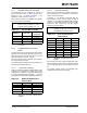
EQUATION 5-2: CALCULATING TRIM
VALUE FROM MEASURED
FREQUENCY
• If the number of error clocks per minute is
negative, then the oscillator is faster than
ideal and the SIGN bit must be cleared.
• If the number of error clocks per minute is
positive, then the oscillator is slower than
ideal and the SIGN bit must be set.
7. Load the correct value into TRIMVAL<6:0>.
5.6.1.2 Calibration by Observing Time
Deviation
To calibrate the MCP7940N by observing the deviation
over time, perform the following steps:
1. Ensure TRIMVAL<6:0> is reset to 0x00.
2. Load the timekeeping registers to synchronize
the MCP7940N with a known-accurate refer-
ence time.
3. Enable the crystal oscillator or external clock
input by setting the ST bit or EXTOSC bit,
respectively.
4. Observe how many seconds are gained or lost
over a period of time (larger time periods offer
more accuracy).
5. Calculate the PPM deviation (see Equation 5-3).
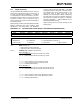
EQUATION 5-3: CALCULATING ERROR
PPM
• If the MCP7940N has gained time relative to
the reference clock, then the oscillator is
faster than ideal and the SIGN bit must be
cleared.
• If the MCP7940N has lost time relative to the
reference clock, then the oscillator is slower
than ideal and the SIGN bit must be set.
6. Calculate the trim value (see Equation 5-4).
EQUATION 5-4: CALCULATING TRIM
VALUE FROM ERROR
PPM
7. Load the correct value into TRIMVAL<6:0>.
Note: Using a lower output frequency and/or
averaging the measured frequency over a
number of clock pulses will reduce the
effects of jitter and improve accuracy.
TRIMVAL<6:0>
F
IDEAL FMEAS–
32768
F
IDEAL
-------------------60
2
---------------------------------------------------------------------------------=
Where:
F
IDEAL Ideal frequency based on SQWFS<1:0>=
F
MEAS Measured frequency=
Note 1: Choosing a longer time period for observ-
ing deviation will improve accuracy.
2: Large temperature variations during the
observation period can skew results.
PPM
SecDeviation
ExpectedSec
----------------------------------- 1 0 0 0 0 0 0=
Where:
ExpectedSec Number of seconds in chosen period=
SecDeviation Number of seconds gained or lost=
TRIMVAL<6:0>
PPM 32768 60
1000000 2
-------------------------------------------=