
Datasheet

2010-2014 Microchip Technology Inc. DS20005010F-page 11
MCP7940N
5.0 FUNCTIONAL DESCRIPTION
The MCP7940N is a highly-integrated Real-Time
Clock/Calendar (RTCC). Using an on-board, low-
power oscillator, the current time is maintained in sec-
onds, minutes, hours, day of week, date, month, and
year. The MCP7940N also features 64 bytes of general
purpose SRAM. Two alarm modules allow interrupts to
be generated at specific times with flexible comparison
options. Digital trimming can be used to compensate
for inaccuracies inherent with crystals. Using the
backup supply input and an integrated power switch,
the MCP7940N will automatically switch to backup
power when primary power is unavailable, allowing the
current time and the SRAM contents to be maintained.
The time-stamp module captures the time when pri-
mary power is lost and when it is restored.
The RTCC configuration and Status registers are used
to access all of the modules featured on the
MCP7940N.
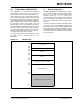
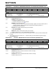
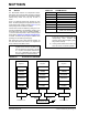
5.1 Memory Organization
The MCP7940N features two different blocks of mem-
ory: the RTCC registers and general purpose SRAM
(Figure 5-1). They share the same address space,
accessed through the ‘1101111X’ control byte.
Unused locations are not accessible. The MCP7940N
will not acknowledge if the address is out of range, as
shown in the shaded region of the memory map in
Figure 5-1.
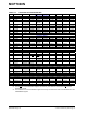
The RTCC registers are contained in addresses 0x00-
0x1F. Table 5-1 shows the detailed RTCC register map.
There are 64 bytes of user-accessible SRAM, located
in the address range 0x20-0x5F. The SRAM is a sepa-
rate block from the RTCC registers. All RTCC registers
and SRAM locations are maintained while operating
from backup power.
FIGURE 5-1: MEMORY MAP
Time and Date
SRAM (64 Bytes)
Power-Fail/Power-Up Time-Stamps
Alarm 1
Alarm 0
Configuration and Trimming
0x00
0x06
0x07
0x09
0x0A
0x10
0x11
0x17
0x18
0x1F
0x20
0x5F
0x60
0xFF
Unimplemented; device does not ACK
I
2
C™ Address: 1101111x
RTCC Registers/SRAM