
User manual

MCP73X23 Lithium Iron Phosphate Battery Charger Evaluation Board User’s Guide
DS51850A-page 8 © 2009 Microchip Technology Inc.
2.3 GETTING STARTED
The MCP73X23 Lithium Iron Phosphate Battery Charger Evaluation Board is fully
assembled and tested for charging LiFePO
4
batteries.
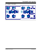
2.3.1 Power Input and Output Connection
2.3.1.1 POWERING THE MCP73X23 LITHIUM IRON PHOSPHATE BATTERY
CHARGER EVALUATION BOARD
1. Connect the positive battery terminal to V
BAT+
and negative battery terminal to
V
BAT-
.
2. Connect the DC power supply Negative Terminal to V
SS
.
3. Connect the DC power supply Positive Terminal to V
DD
.
4. It should initiate the battery charging cycle when the power source is present and
V
BAT
is below recharge threshold. For example, When V
REG
is 3.6V, V
BAT
needs
to be lower than 3.42V to initiate the charge cycle.
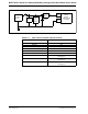
5. The charging status table is available on Table 2-2.
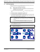
6. The fast charge current is preset at 500 mA and can be increased to 1A by
connecting PROG via to ground.
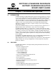
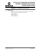
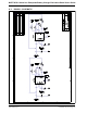
FIGURE 2-1: Board Top Assembly.
Note 1: The MCP73123 circuit is designed to charge one-cell LiFePO
4
battery
and the MCP73223 circuit is designed to charge two-cell LiFePO
4
battery.
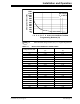
2: The LiFePO
4
battery can be replaced with test circuit or electronic load
that can sink current with DC power supply. Refer to Figure 2-3.
Note: Fast Charge Current can be programmed with various resistors based on
Figure 2-2 and Table 2-2.
1