
Datasheet

MCP73871 Evaluation Board User’s Guide
DS51755A-page 8 © 2008 Microchip Technology Inc.
2.3 GETTING STARTED
The MCP73871 Evaluation Board is fully assembled and tested for charging a
single-cell Li-Ion or Li-Polymer battery with or without system load.
2.3.1 Power Input and Output Connection
2.3.1.1 POWERING THE MCP73871 EVALUATION BOARD
1. Connect the positive battery terminal to V
BAT+
(TP4) and negative battery
terminal to V
SS
(TP1 or TP5).
2. Connect the 5V - 6V DC power supply Negative Terminal to V
SS
(TP1 or TP5).
3. Connect the 5V - 6V DC power supply Positive Terminal to V
DD
(TP2).
4. Connected positive of load to OUT (TP3) on the board and negative of load to
either V
SS
(TP1 or TP5). The system load can be a power resistor or E-Load.
5. The maximum current that system load requires should not violate the specifica-
tion of Li-Ion battery manufacturer (Typical at 1C or less) or 1A for safety and
performance concerns.
6. It should initiate the battery charging cycle when drive CE (TP6) high. Drive CE
(TP6) low disables the Li-Ion battery charger function.
7. Position the DIP Switch #2 (SW2) to “AC” allows maximum input current of 1.8A
to support both system load and Li-Ion battery charger at 1000 mA fast charge
current rate.
8. Position the DIP Switch #2 (SW2) to “USB” limits the input current to meet USB
specifications.
9. When DIP Switch #2 (SW2) is positioned at USB; position the DIP Switch #1
(SW1) to “High” limits total input current to 500 mA and “Low” for maximum input
current at 100 mA.
10. Remove DC power supply, the load should be supported by the Li-Ion battery
now.
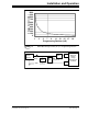
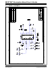
Note: Fast Charge Current and Termination Current can be easily programmed
with various resistors that based on the Figure 2-1.
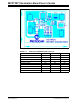
The Li-Ion battery pack can be replaced with test circuit or electronic load
that can sink current with DC power supply. Please refer to Figure 2-2.