
Datasheet


MCP73871 Evaluation Board User’s Guide
DS51755A-page 6 © 2008 Microchip Technology Inc.
1.2 WHAT IS THE MCP73871 EVALUATION BOARD?
The MCP73871 Evaluation Board demonstrates the features of Microchip’s MCP73871
“Stand-alone Linear Li-Ion / Li-Poly Battery Charge and System Load Sharing Manage-
ment Controller”.
The MCP73871 Evaluation Board is designed to deliver minimum 1.5A total current to
system load and to a single cell Li-Ion battery at 4.2V preset voltage regulation. (4.1V,
4.35V and 4.4V options are also available for MCP73871) The MCP73871 Evaluation
Board has two dip switches to control input current limits. First dip switch (SW2)
determines input power source between ac-dc adapter and USB port (AC/USB).
Second dip switch (SW1) determines 500 mA high power USB port or 100 mA low
power USB port (High/Low). The input current limit is governed by USB specification
when selecting USB on SW2.
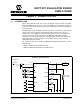
The maximum fast current when AC is selected on SW2 is programmed by resistor
(R
PROG1
) at 1A and termination current is set at 100 mA by (R
PROG3
).
The MCP73871 Evaluation Board offers three status LED for two charge status outputs
and a power good indicator.
The MCP73871 Evaluation Board comes with factory preset low battery indicator
(LBO) when input is absent. The preset value is 3.1V and STAT1 LED turns on when
battery voltage is below the threshold voltage.
The MCP73871 Evaluation Board is designed to observe the performance and features
on the circuits via multiple test points. Circuits can also be implemented into suitable
applications without additional work.
1.3 WHAT THE MCP73871 EVALUATION BOARD KIT INCLUDES
This MCP73871 Evaluation Board kit includes:
• MCP73871 Evaluation Board, 102-00183
• Analog and Interface Products Demonstration Boards CD-ROM (DS21912)
- MCP73871 Evaluation Board User’s Guide User’s Guide (DS51755)
- MCP73871 Data Sheet, “Stand-Alone Linear Li-Ion / Li-Poly Battery Charge
and System Load Sharing Management Controller” (DS22090)
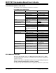
Note: Please refer to Table 2-1 for charge status outputs and Figure 2-1 for
charge current setups.
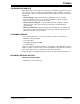
Note: For evaluation LBO purpose, connect a DC power supply and set V
DD
below UVLO. The LBO lights up when V
BAT
drops below threshold voltage.