
Information

23
Portable Power Conversion Design Guide
Battery Management
Programmable Battery Chargers
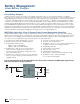
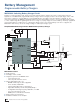
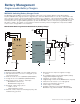
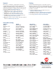
MCP1631 Switching Battery Charger Circuit
The MCP1631 Analog PWM Controller with integrated ×10 current sense amplifier, Battery Voltage Divider Buffer
Amplifier, MOSFET driver, high-speed Over Voltage Detection and Pulse Width Modulation controller, combined with a PIC
microcontroller, is used to develop intelligent battery chargers. The combination of the dedicated analog PWM controller
with a PIC MCU creates highly versatile charging solutions. The MCP1631HV provides the analog circuitry needed to drive
several power train topologies (SEPIC, Flyback, Boost) while the PIC MCU is used to develop the programmable charge
algorithm to adapt to the number of series batteries and their chemistry. The block diagram below represents a SEPIC
solution used to charge NiMH or Li-Ion batteries.
MCP1631HV SEPIC Programmable Multi-Chemistry Battery Charger
MCP1631 Features
STATUS
Li-Ion
NiMH
ICSP
OSC
V
REF
V
DD
VBATT
VEXT
VFS
CS
OV
GND
+V
IN
GND
J
5
+VDD
+VBATT
–VBATT
Temp_Sense
LED 1...4
PIC
®
MCU MCP1631HV
VBATT
OV
■ High-speed analog PWM controller (2 MHz operation)
■ Can pair with a microcontroller for “Intelligent” power
system development
■ Peak current mode control (MCP1631/MCP1631HV)
■ Voltage mode control (MCP1631V/MCP1631VHV)
■ High voltage options operate to +16V input:
• MCP1631HV current mode
• MCP1631VHV voltage mode
■ Regulated output voltage options:
• +5.0V or +3.3V
• 250 mA maximum current
■ External oscillator input sets switching frequency and
maximum duty cycle limit
■ External reference input sets regulation voltage
or current
■ Error amplifier, battery current ISNS amplifier, battery
voltage VSNS amplifier integrated
■ Integrated over-voltage comparator
■ Integrated high current low side MOSFET driver (1A peak)
■ Shutdown mode reduces Iq to 2.4 µA (typical)
■ Internal over-temperature protection
■ Under-voltage lockout (UVLO)
■ Available in 20-lead 4 × 4 mm QFN (MCP1631/
MCP1631V only), 20-lead TSSOP or 20-lead SSOP