
Information

18
Portable Power Conversion Design Guide
Backlighting Solutions
Switching Regulators
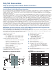
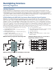
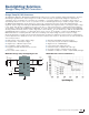
MCP16312 Buck Converter LED Application
The MCP16312 buck converter can be used as a constant current source to drive one or more LEDs. Starting from the
standard buck circuit, the anode of the LED load is connected at the buck coverter output. Using a sense resistor between
the LED cathode and ground will produce a constant voltage at constant current, and this voltage can be used as the
feedback signal into the buck converter. The control loop in the MCP16312 will adjust the duty cycle of the internal MOSFETs,
regulating to a constant voltage on the sense resistor, corresponding to a constant output current in the LED string.
MCP16312 Buck Converter LED Application Circuit
MCP16301 C
´
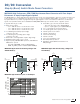
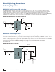
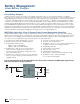
uk LED Application
While it is typically operated as a buck regulator, the MCP16301 can be creatively designed into a low component count
C
´
uk circuit. It will operate from 6 V to 18 V in, producing a regulated output and supplying up to 300 mA of current. This is
an excellent solution for LED drive applications, capable of driving multiple LEDs in series (up to 15V). Due to both the low
number of components (as few as eleven) and readily available small size surface mount component options (mostly 0603
surface mount packages), this design can be implemented in a very small board area.
This circuit is implemented in the MCP16301 High Voltage Single Inductor C
´
uk LED Demo Board, available
through Microchip.
MCP16301 C
´
uk Converter Circuit
GND
V
IN
VCC
EN
BOOST
V
FB
SW
COUT
2 ×10 μF
C
IN
2 ×10 μF
1 × White
LED
R
B = 2Ω
ILED
= 400 mA
V
IN = 12V
REN
1 MΩ
C
VCC
1 μF
RB =
V
FB
ILED
CBOOST
0.1 μF
L
1
15 μH
GND
V
IN
VFB
EN
BOOST
SW
4.7 μF
V
IN
6V to 18V
C
BOOST
100 nF
33 μH
0.47 μF
−V
OUT
1N4148
−VOUT
2.2 nF
40V
Schottky
Diode
2.7Ω 150 kΩ