
Information

15
Portable Power Conversion Design Guide
AAAA Battery Boost Circuit
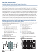
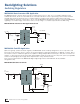
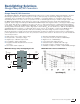
An MCP1640 boost converter and PIC12F microcontroller can create a simple power solution which will deliver a 3.3V
output from a single alkaline battery cell, with very low power consumption and long battery run time, especially in low-
current applications. The circuit will run in standby mode, with the PIC12F617 in sleep mode and the MCP1640 disabled,
consuming only a few μA from the battery (in shutdown mode the MCP1640 typically consumes 0.75 μA). A charged
capacitor will maintain the output until the comparator on the PIC® microcontroller detects a low voltage. If the output
capacitor voltage drops too far, the PIC microcontroller will turn on the MCP1640, which will operate normally until the
output capacitor is charged, and then the microcontroller will disable the boost converter again. When the MCP1640 is in
normal operating mode, the no load input current is approximately 70 μA at 1.5V input. By pulsing the MCP1640’s enable
at low frequency, this method reduces the average input current by up to 80%.
This circuit is implimented in the MCP1640 Single Quadruple-A Battery Boost Converter Reference Design, available
through Microchip.
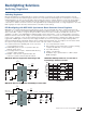
MCP1640 Single Quadruple-A Battery Boost
Coverter Demonstration Board (MCP1640RD-4ABC)
MCP1640 Boost Converter Reference
Design Circuit
I/O
A/D
I/O
I/O
I/O
V
DD
Load Switch
P-MOS
Single Quadruple-A Battery Input
PIC12F617
VOUT
VIN
EN
MCP1640
ON/OFF
S
1
1
2
Status
LED
Load
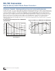
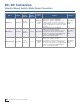
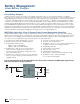
MCP1640 Boost Converter Reference Design
Behavior During Operation
*
MCP1640 Boost Converter Reference Design No
Load Input Current
10
15
20
25
30
0.8 1 1.2 1.4 1.6
Standby No Load Input
Current (µA)
Input Voltage (V)
DC/DC Conversion
Step-Up (Boost) Switch Mode Power Converters