
Information

12
Portable Power Conversion Design Guide
DC/DC Conversion
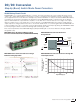
Step-Up (Boost) Switch Mode Power Converters
Step Up (Boost) Switch Mode Power Converters
Boost converters increase the unregulated input voltage to a regulated output (unlike buck converters, which always reduce
the input voltage). Conceptually, both types of circuits use switched electromagnetic components to store energy and
maintain efficiency. Boost converters are commonly used in single- and two-cell Alkaline, NiMH and new non-rechargeable
lithium battery applications.
Microchip offers several boost converter solutions with integrated MOSFETs that are capable of starting and operating from a
single-cell battery (0.8V input, or less in some cases). Many devices offer pulse width modulation (PWM) and pulse frequency
modulation (PFM) modes of operation. PWM mode switches at constant frequency to minimize output ripple and noise while
delivering high-efficiency power conversion at high output loads. PFM mode dynamically reduces the switching frequency,
sometimes even allowing increased the output ripple, in order to dramatically reducing switching losses and improve efficiency
in light load conditions. Taking advantage of these functions, the MCP1640 and MCP16251/2 device families (and many
other Microchip parts) can automatically transition between PFM and PWM as the output current demand changes. In some
applications, the output ripple introduced by PFM mode may be too noisy for the desired circuit performance. For these
designs, the MCP1640B device can operate in PWM mode only, providing a low output ripple voltage and reducing electrical
noise. Many of these boost regulators can be disabled with a shutdown input signal; several are available with true load
disconnect (open the circuit from input to output) or with bypass (connected input and output) operation during shutdown.
Integrated boost converters are small-footprint, high-efficiency power conversion solutions for many portable applications.
MCP16251 Ultra-Low Quiescent Current, PFM/PWM Synchronous Boost Regulator with
True Output Disconnect or Input/Output Bypass Options
One of the advantages of the MCP16251/2 over other boost regulators is its low quiescent current (4 µA). This, combined
with the PFM mode operation and a high resistance feedback voltage divider, results in a converter that greatly increases
the run time of battery-powered applications at low load.
■ Typical efficiency up to 96%
■ High current output:
• I
out > 100 mA at Vout = 3.3V and Vin = 1.2V
• Iout > 250 mA at Vout = 3.3V and Vin = 2.4V
• Iout > 225 mA at Vout = 5.0V and Vin =3.3V
■ Ultra-low device quiescent current:
• Output quiescent current less than 4 µA typical
(device is not switching, Vout > Vin)
• Input sleep current less than 1 µA
(device is not switching, Vout > Vin, no load)
• Typical no load input current of 14 µA
(device is switching)
• 0.6 µA typical shutdown current
■ Low 0.82V start-up voltage
■ Low 0.35V minimum operating input voltage
■ Maximum input voltage ≤ Vout < 5.5V
■ Adjustable output from 1.8V to 5.5V
■ 1.23V feedback voltage
■ Automatic PFM/PWM operation:
• 500 kHz PWM operation
• 100 mV typical PFM output ripple
■ Internal synchronous rectifier
■ Internal compensation
■ Inrush current limiting
■ Internal soft-start (1.5 ms typical)
■ Selectable, logic-controlled shutdown states:
• True load disconnect option (MCP16251)
• Input to output bypass option (MCP16252)
■ Anti-ringing control
■ Over-temperature protection
■ Available in 6-lead SOT-23 and 8-lead 2 × 3 TDFN
packages
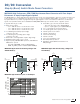
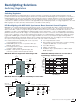
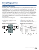
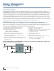
MCP16251 Typical Application Circuit
GND
V
IN
EN
SW
V
FB
VOUT
VOUT
3.3V
V
IN
0.9V
TO 1.7V
COUT
10 μF
C
IN
4.7 μF
1.69 MΩ
1 MΩ
L
1
4.7
μH
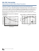
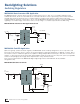
MCP16251 Typical Circuit Efficiency
50
55
60
65
70
75
80
85
90
95
100
0.1 1 10 100 1000
Efficiency (%)
I
OUT
(mA)
V
OUT
= 3.3V
V
IN
= 1.5V
V
IN
= 2.4V
V
IN
= 3.0V