Analog and Interface Solutions Portable Power Conversion Design Guide www.microchip.
Design Guide Introduction and Contents Portable power conversion applications present unique and challenging design considerations. Innovative, small electronics require solutions with small footprints. In order to maintain battery life, portable applications require both high conversion efficiency and low standby power dissipation.
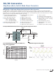
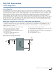
DC/DC Conversion Step-Down (Buck) Switch Mode Power Converters MCP16301/H 36V Input Voltage Non-Synchronous Buck Converter The MCP16301 is a highly integrated, high-efficiency, fixed-frequency, step-down DC-DC converter in a popular 6-pin SOT-23 package. This converter operates from voltage sources up to 30V, including the integrated high-side switch, fixed-frequency Peak Current Mode Control, internal compensation, peak current limit and over-temperature protection.
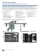
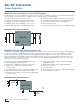
DC/DC Conversion Step-Down (Buck) Switch Mode Power Converters MCP16311/2 30V Input, High-Efficiency, Integrated Synchronous Buck Regulator The MCP16311 is a compact, high-efficiency, fixed-frequency PWM/PFM, synchronous step-down DC-DC converter in a 8-pin MSOP or 2 × 3 TDFN package that operates from input voltage sources up to 30V.
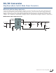
DC/DC Conversion Step-Down (Buck) Switch Mode Power Converters MCP16311 12V Buck-Boost Application Some power supplies require the ability step the voltage up or down from the input to the output. This is particularly useful in battery-powered applications where the battery voltage may be above or below the desired output voltage, depending on the type of battery used or battery charge remaining.
DC/DC Conversion Step-Down (Buck) Switch Mode Power Converters MCP16323 3A Synchronous Buck DC/DC Converter The MCP16323 is a fully integrated synchronous buck dc/dc converter that operates from 6V to 18V input, regulates the output voltage to any level between 0.9V to 5V, and supplies load currents up to 3A. Operating at a fixed 1 MHz switching frequency offers small external inductor and capacitor sizes, minimizing board space.
DC/DC Conversion Step-Down (Buck) Switch Mode Power Converters MCP1603/L/B Synchronous Buck Regulators The MCP1603 is a family of highly efficient, fully integrated 500 mA synchronous buck regulators. The 2.7V to 5.5V input range makes these ideally suited for battery powered applications, including one-cell Li-ion; two- or three-cell NiMH; or twoor three-cell NiCd power sources. With heavy loads, the MCP1603/L operates in a 2.
DC/DC Conversion Step-Down (Buck) Switch Mode Power Converters Input Voltage Range (V) Output Voltage Range (V) Control Scheme 0.8–4.
DC/DC Conversion Linear Regulators Linear Regulators Linear regulators provide a precise regulated voltage to the system load from a varying input voltage source. Compared to switching regulators, they are generally smaller, simpler, and can benefit from reduced electrical noise. They are generally less efficient than buck regulators, but for small voltage changes or low currents the absolute power losses may be small. There are trade-offs when selecting the proper LDO.
DC/DC Conversion Linear Regulators MCP1710 Ultra-Low Quiescent Current LDO Regulator The MCP1710 is low dropout (LDO) linear regulator that provides up to 200 mA of current to the load while maintaining an ultra-low 20 nA of quiescent current consumption, and it comes in a tiny 2 × 2 DFN package. ■■ ■■ ■■ ■■ ■■ ■■ ■■ ■■ ■■ ■■ Ultra-low 20 nA (typical) quiescent current Ultra-low 0.1 nA typical shutdown supply current 200 mA output current capability for Vout < 3.
DC/DC Conversion Linear Regulators Device MCP1700 Max. Input Voltage (V) Output Voltage Range (V) Output Current (mA) 6.0 1.2–5.0 250 Typical Typical Dropout Quiescent Voltage at Max. Current (μA) Iout (mV) 1.6 Features Packages 178 Shutdown, power good output with adjustable delay 3-pin SOT-23A, 3-pin SOT-89, 3-pin TO-92 3-pin 3-pin 3-pin 8-pin SOT-23A, SOT-89, SOT-223, 2 × 3 DFN MCP1703A 16 1.2–5.0 250 2 625 Low quiescent current, low ground current in dropout MCP1710 5.5 1.2–4.
DC/DC Conversion Step-Up (Boost) Switch Mode Power Converters Step Up (Boost) Switch Mode Power Converters Boost converters increase the unregulated input voltage to a regulated output (unlike buck converters, which always reduce the input voltage). Conceptually, both types of circuits use switched electromagnetic components to store energy and maintain efficiency. Boost converters are commonly used in single- and two-cell Alkaline, NiMH and new non-rechargeable lithium battery applications.
DC/DC Conversion Step-Up (Boost) Switch Mode Power Converters MCP1640 High Performance PFM/PWM Synchronous Boost Converter with True Output Disconnect or Input/Output Bypass Options The MCP1640 is a compact, high-efficiency, fixed-frequency, synchronous step-up DC-DC converter. It provides an easy-to-use power supply solution for applications powered by one-, two-, or three-cell alkaline, NiCd, NiMH; one-cell Li-ion; or one-cell Li-polymer batteries.
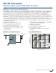
DC/DC Conversion Step-Up (Boost) Switch Mode Power Converters Performance Tradeoffs – Matching the Boost Converter to the Load Requirements In many cases, light or no load conditions have very different requirements than high load conditions. This tradeoff can be readily observed by comparing the MCP1640 and MCP16251. The MCP1640 offers higher current capability, handing peak loads up to 350 mA compared to only 225 mA for MCP16251.
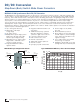
DC/DC Conversion Step-Up (Boost) Switch Mode Power Converters AAAA Battery Boost Circuit An MCP1640 boost converter and PIC12F microcontroller can create a simple power solution which will deliver a 3.3V output from a single alkaline battery cell, with very low power consumption and long battery run time, especially in lowcurrent applications.
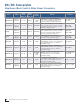
DC/DC Conversion Step-Up (Boost) Switch Mode Power Converters Device MCP1623/4 MCP16251/2 MCP1640/B/C/D 16 Output Adjustable Adjustable Adjustable Input Voltage Range (V) 0.35/ 0.65–5.0 0.35/ 0.82–5.0 0.35/ 0.65–5.0 Portable Power Conversion Design Guide Output Voltage Range (V) 2–5.5 1.8–5.5 2–5.
Backlighting Solutions Switching Regulators Switching Regulators Efficient backlighting in portable applications presents a number of unusual power supply design challenges. Like all portable circuits as in all portable designs, board area is at a premium and minimizing power consumption is essential for maximizing battery run time.
Backlighting Solutions Switching Regulators MCP16312 Buck Converter LED Application The MCP16312 buck converter can be used as a constant current source to drive one or more LEDs. Starting from the standard buck circuit, the anode of the LED load is connected at the buck coverter output. Using a sense resistor between the LED cathode and ground will produce a constant voltage at constant current, and this voltage can be used as the feedback signal into the buck converter.
Backlighting Solutions Charge Pump DC/DC Converters Charge Pump DC/DC Converters The MCP1256, MCP1257, MCP1258 and MCP1259 are inductorless, positive regulated charge pump DC/DC converters. Generating a regulated 3.3V output voltage from a 1.8V to 3.6V input, they are specifically designed for applications operating from two-cell alkaline, two-cell Ni-Cd, two-cell Ni-MH, or one primary lithium coin cell battery. These devices automatically switch from 1.
Battery Management Linear Battery Chargers Linear Battery Chargers In battery-powered systems, the quality of the charging circuit plays a key role in the life and reliability of the battery. Microchip offers a complete line of linear Li-Ion battery chargers. To further reduce design size, cost and complexity, the Li-Ion Charge Management Controllers provide a reliable, low-cost and high accuracy voltage regulation solution with few external components.
Battery Management Linear Battery Chargers MCP73113, MCP73123: Battery Charge Management Controllers In addition to the features of the MCP73830, these battery chargers also include charge status outputs, over-voltage protection and more options for end-of-charge thresholds, safety timers and charge currents. Also available are the MCP73213 (Li-ion) and MCP73223 (LiFePO4), with higher voltage capabilities to charge two cells in series. ■■ Programmable charge current: 130 mA to 1.
Battery Management Programmable Battery Chargers MCP19111 Switching Battery Charger Circuit Designs for wide input range, high output power multi-chemistry battery chargers are used for many battery-powered applications. The MCP19111 programmable battery charger reference design operates from an input range of 6V to 28V and can be configured to charge NiMH, Li-Ion and LiFeO4 batteries in multiple series and parallel configurations.
Battery Management Programmable Battery Chargers MCP1631 Switching Battery Charger Circuit The MCP1631 Analog PWM Controller with integrated ×10 current sense amplifier, Battery Voltage Divider Buffer Amplifier, MOSFET driver, high-speed Over Voltage Detection and Pulse Width Modulation controller, combined with a PIC microcontroller, is used to develop intelligent battery chargers. The combination of the dedicated analog PWM controller with a PIC MCU creates highly versatile charging solutions.
Related Support Material Application Notes The following application notes are available on the Microchip web site: www.microchip.com. AN793: Power Management in Portable Applications: Understanding the Buck Switch Mode Power Converter This is an in-depth application note describing the design of buck topology switch mode power supplies for use in portable applications.
Related Support Material Evaluation Boards Microchip offers a number of boards to help evaluate device families. Contact your local Microchip sales office for a demonstration. AAAA Clock Demo A PIC microcontroller performs basic clock functions on a LCD display using a single AAAA battery boosted up to 3.3V using a MCP1624. The demo includes capacitive touch controls and battery fuel measurement.
Related Support Material MCP16323 Evaluation Board (ADM00427) This small footprint, high-current-density buck circuit provides up to 3A at 3V from an input voltage between 6.0 and 18V. MCP1640 12V/50 mA Two Cells Input Boost Converter Reference Design (ARD00386) Using inputs between 2.0 and 5.0V typical of a two-cell battery pack, this MCP1640 boost converter can generate high 9, 12 or 24V outputs.
Related Support Material Also Check the Following Demonstration Boards on Our Website UCS1001 Evaluation Board (ADM00540) MCP16301 High-Voltage Single-Inductor Ćuk LED Driver Demo Board (ARD00410) UCS1002 Programmable USB Port Power Evaluation Board (ADM00497) MCP1632 300 kHz Boost Converter Demo Board (ADM00530) MCP1256/7/8/9 Charge Pump Evaluation Board (MCP1256/7/8/9EV) MCP1710 Demo Board (ADM00468) MCP1601 Buck Regulator Evaluation Board (MCP1601EV) MCP73213 OVP Dual-Cell Li-Ion Battery Charger
Support Training Microchip is committed to supporting its customers in developing products faster and more efficiently. We maintain a worldwide network of field applications engineers and technical support ready to provide product and system assistance. In addition, the following service areas are available at www.microchip.com: ■■ Support link provides a way to get questions answered fast: http://support.microchip.com ■■ Sample link offers evaluation samples of any Microchip device: http://sample.