
Information
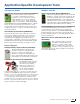
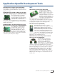
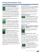

MCP6V01 Thermocouple Auto-Zeroed Reference
Design Board (MCP6V01RD-TCPL)
The MCP6V01 Design Board
demonstrates how to use a difference
amplifier system to measure
Electromotive Force (EMF) voltage
at the cold junction of thermocouple
in order to accurately measure temperature of the
thermocouple bead. The MCP6V01 auto-zeroed op amp,
with its ultra low-offset voltage (VoS) and high Common
Mode Rejection Ratio (CMRR), provides a way to capture
this measurement.
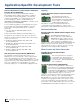
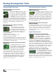
MCP661 Low-Driver Demonstration Board
(MCP661DM-LD)
This demonstration board uses the
MCP661 in a very basic application
for high-speed op amps: a 50Ω
line (coax) driver. It gives a 30 MHz
solution, high-speed PCB layout techniques and a means
to test AC response, step response and distortion. Both
the input and the output are connected to lab equipment
with 50Ω BNC cables. There are 50Ω terminating resistors
and transmission lines on the board. The op amp is set to
a gain of 2V/V to overcome the loss at its output caused
by the 50Ω resistor at that point. Three surface mount
test points make it simple to connect lab supplies to
the board.
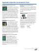
Motor Drivers
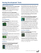
MTS2916A Dual Full-Bridge Stepper Motor Driver
Evaluation Board (ADM00308)
The MTS2916A Dual Full-Bridge
Stepper Motor Driver Evaluation Board
demonstrates how the MTS2916A
controls both windings of a bipolar stepper
motor. The board also demonstrates the
capabilities of the MTS62C19A, which has the same
functionality but different pin assignments. A PIC16F883
is utilized for motor control processing. Push button
switches and a variable-speed input potentiometer can
be used to exercise a stepper motor in Full-Step, Half-
Step, Modified Half-Step and Microstepping modes. LEDs
indicate a binary representation of which mode has been
selected. The evaluation board and the stepper motor can
be powered from a single power input J1 (7 VDC to 12
VDC) with jumper JP2 installed. For higher motor voltages,
make sure JP2 is not installed, and connect VLOAD at J4.
Numerous test points have been designed into the board
to allow easy access.
Analog Development Tools
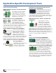
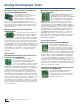
MCP8025 TQFP BLDC Motor Driver Evaluation
Board (ADM00600)
The MCP8025 TQFP BLDC Motor Driver
Evaluation Board demonstrates the
MCP8025 3-Phase Brushless DC (BLDC)
Motor Gate Driver with Power Module
used in a BLDC motor drive application.
When used in conjunction with a microcontroller, the
MCP8025 will provide the necessary signals to drive a
3-phase BLDC motor. The MCP8025 contains the high-
side and low-side drivers for external N-channel MOSFETs.
A dsPIC33EP256MC504 processor is used to supply
the PWM inputs to the MCP8025 as well as handle the
high-speed ADC required for 50 kHz PWM operation.
The MCP8025 UART interface is used to configure the
MCP8025 device and to send fault information to the
dsPIC DSC. The evaluation board firmware uses a 6-step
trapezoidal drive control algorithm to demonstrate the
MCP8025's capabilities.
Power Management
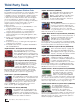
MCP19111 Evaluation Board (ADM00397)
The MCP19111 Evaluation Board
demonstrates how the MCP19111 device
operates in a synchronous buck topology
over a wide input voltage and load range.
Nearly all operational and control system
parameters are programmable by utilizing the
integrated PIC microcontroller core. MPLAB X IDE can be
used in conjunction with a Graphical User Interface (GUI)
plug-in to easily configure the MCP19111. Alternatively,
you can program the MCP19111 using your own firmware,
tailoring it to your application. The evaluation board
contains headers for In-Circuit Serial Programming™ (ICSP)
as well as I
2
C communication, pull-up and pull-down resistor
pads and test point pads on each GPIO pin, and two push
buttons for system development.
MCP19035 300 kHz Synchronous Buck Controller
Evaluation Board (ADM00434)
The MCP19035 300 kHz Synchronous
Buck Controller Evaluation Board
provides a compact, low-cost and highly
efficient step-down conversion for low- to
medium-output currents.
When used in conjunction with a microcontroller, the
18
Quick Guide to Microchip Development Tools