
Information


The HV9961DB1 LED driver features tight regulation of the
LED current within a few milliamps over the entire range
of the input AC line and the output LED string voltage.
The LED current accuracy is almost insensitive to the
passive component tolerances, such as the output filter
inductance or the timing resistor. The accuracy of the
LED current is mainly determined by the internal 275 mV
± 3% reference voltage of the HV9961 control IC and by
the external current sense resistor tolerance. The output
current can be adjusted down to 60 mA using an on-board
potentiometer. However, the accurate current control is
only achieved with continuous conduction of the filter
inductor, i.e. when the LED current is greater than the
inductor ripple current amplitude.
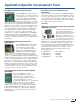
Universal Off-Line, High-Brightness 350 mA LED
Driver Demonstration Board (HV9910BDB2)
The HV9910BDB2 demonstration board is a
high-brightness LED power driver to supply
a string of LEDs using the HV9910B IC from
a universal AC input. The HV9910BDB2
can supply a maximum output current of 350 mA to
drive 10–40V LED strings from a wide input voltage of
−90 to 265 VAC, 50/60 Hz. The power conversion stage
of the HV9910BDB2 consists of a diode bridge rectifier,
followed by a current-controlled buck converter operating
at a switching frequency of 50 kHz. The nominal output
current of the demonstration board can be adjusted to
any value between 30 and 350 mA using the on-board
trimming potentiometer. PWM dimming can be achieved
by applying a pulse-width-modulated square wave signal
between the PWMD and GND pins. Zero output current can
be obtained only by PWM dimming.
Operational Amplifi ers
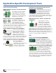
MCP6N11 and MCP6V2X Wheatstone Bridge
Reference Design (ARD00354)
This board demonstrates the performance
of the MCP6N11 instrumentation amplifier
(INA) and a traditional three op amp INA
using the MCP6V26 and MCP6V27 auto-
zeroed op amps. The input signal comes
from an RTD temperature sensor in a
Wheatstone bridge. Real-world interference is added
to the bridge’s output to provide realistic performance
comparisons. Data is gathered and displayed on a PC
for ease of use. The USB microcontroller and included
Graphical User Interface (GUI) allow you to configure the
board and collect sample data.
Digital-to-Analog Converters
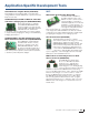
MCP4725 SOT-23-6 Evaluation Board (MCP4725EV)
The MCP4725 SOT-23-6 Evaluation Board
is a quick and easy evaluation tool for
the MCP4725 12-bit DAC device. It works
with our popular PICkit Serial Analyzer or
independently with your applications board. The PICkit
Serial Analzyer is sold separately.
MCP4728 Evaluation Board (MCP4728EV)
This evaluation board allows quick and easy evaluation of
the MCP4728 4-channel 12-bit DAC device. It contains the
MCP4728 device and connection pins for the PICkit Serial
Analyzer. When the MCP4728 evaluation board is connected
to the PICkit Serial Analyzer and the DAC input data is
entered into the PC Graphical User Interface program,
the serial analyzer automatically sends your data to the
DAC device.
Power Monitoring
MCP39F501 Power Monitor PICtail Evaluation
Board (ADM00509)
The MCP39F501 Power Monitor PICtail
Evaluation Board serves as a fully
functional single-phase power monitor
and development platform. This low-cost
design does not use any transformers and
requires few external components. The device calculates
active power, reactive power, RMS current, RMS voltage,
power factor, line frequency and other typical power
quantities as defined in the MCP39F501 data sheet. The
MCP39F501 Power Monitor Utility software is used to
calibrate and monitor the system and can be used to create
custom calibration setups. Only a single point of calibration
may be needed for some accuracy requirements.
I/O Expanders
MCP23X17 16-bit GPIO Expander Evaluation Board
(MCP23X17EV)
This board demonstrates the simple input/
output functionality of the MCP23017
(I
2
C interface) and the MCP23S17 (SPI
interface). The system demonstrates the
simplicity of monitoring four pins configured as inputs and
applying a predetermined pattern on LEDs connected to the
remaining 12 pins configured as outputs.
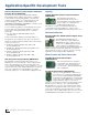
LED Drivers
21-Watt Universal AC LED Driver Demonstration
Board with Accurate Average-Mode Constant
Current Control (HV9961DB1)
The HV9961 demonstration board is a high-
brightness LED driver employing the average-
mode constant current control scheme. The
power conversion stage of the HV9961DB1
consists of a diode bridge rectifier followed by
a buck converter operating with fixed off-time of 20 μs.
requires few external components. The device calculates
Analog Development Tools
17
Quick Guide to Microchip Development Tools