
Information

Analog Development Tools
Analog-to-Digital Converters
MCP3421 Weight Scale Demo Board
(MCP3421DM-WS)
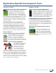
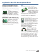
The MCP3421 Weight Scale Demo Board
allows you to evaluate the performance of
the low-power consumption, 18-bit ADC in
an electronic weight scale design. Next to
the MCP3421 there is a low-noise, auto-
zero MCP6V07 op amp. This can be used
to investigate the impact of extra gain
added before the ADC for performance improvement. The
PIC18F4550 controls the LCD and the USB communication
with the PC. The GUI is used to indicate the performance
parameters of the design and for calibration of the
weight scale.
MCP3421 Battery Fuel Gauge Demo Board
(MCP3421DM-BFG)
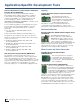
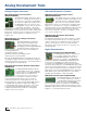
The MCP3421 Battery Fuel Gauge
Demo Board demonstrates how to
measure the battery voltage and
discharging current using the MCP3421.
The MCU algorithm calculates the
battery fuel being used. The demo board displays the
following parameters:
(a) Measured battery voltage
(b) Measured battery discharging current
(c) Battery fuel used (calculated)
Although the MCP3421 Battery Fuel Gauge Demo Board
can charge a single-cell 4.2V Li-Ion battery, this feature is
disabled by firmware since the demo kit is shipped with a
non-rechargeable 1.5V AAA battery.
MCP3910 ADC Evaluation Board for 16-bit MCUs
(ADM00425)
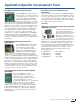
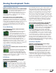
The MCP3910 ADC Evaluation Board
for 16-bit MCUs allows you to evaluate
the performance of the MCP3910 dual-
channel ADCs in a multiple-device,
isolated system. It comes with four
MCP3910s, three of which are isolated and operate
in 2-wire Serial Interface Mode. It also provides a
development platform for 16-bit PIC microcontroller-
based applications, using existing 100-pin PIM systems
compatible with the Explorer 16 and other high pin
count PIC MCU demo boards. The system comes with
programmed PIC24FJ256GA110 PIM modules that
communicate with the PC software for viewing data
samples sent from the board.
CAN and LIN Interface Products
MCP2515 PICtail Plus Daughter Board
(MCP2515DM-PTPLS)
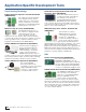
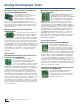
This daughter board is a simple Controller
Area Network (CAN) board designed to be
used with boards containing the PICtail
Plus connector. The board also has the
PICkit Serial connector for interfacing to the PICkit Serial
Analyzer tool. The CAN node consists of the MCP2515
stand-alone CAN controller and MCP2551 CAN transceiver.
The PICkit Plus and PICkit Serial connectors allow the
board to be interfaced to a variety of PIC MCUs to allow
you to develop a CAN node.
MCP2515 CAN Bus Monitor Demo Board
(MCP2515DM-BM)
The MCP2515 CAN Bus Monitor Demo Board kit contains
two identical boards which can be connected together to
create a simple two-node CAN bus. These boards which
can be controlled and/or monitored via the included
PC interface. The board(s) can also be connected to an
existing CAN bus.
Digital Potentiometers
MCP401X Evaluation Board (MCP401XEV)
The MCP401XEV Evaluation Board allows
you to quickly evaluate the operation of
the MCP40D18 Digital Potentiometer.
This device is similar to the MCP40D17,
MCP40D19, MCP4017, MCP4018 and MCP4019. The
board uses the SC70EV generic PCB and has been
populated for the MCP40D18. The 6-pin header (PICkit
Serial) has been jumpered to the MCP40D18’s appropriate
pins. This allows the PICkit Serial to communicate with the
device. The User's Guide includes demonstrations of the
PICkit Serial controlling the MCP40D18 device. Additional
blank PCBs may be ordered by using the order number
SC70EV. Each SC70EV kit contains five PCBs.
MCP43XX Evaluation Board (MCP43XXEV)
The MCP43XX Evaluation Board allows
you to quickly evaluate the operation
of the MCP4361 Digital Potentiometer.
The board uses the TSSOP20EV
Generic PCB and has been populated for the MCP4361.
The 6-pin header (PICkit Serial) has been jumpered to the
MCP4361’s appropriate pins. This allows the PICkit Serial
Analyzer to communicate with the device.
16
Quick Guide to Microchip Development Tools