Analog and Interface Products Analog and Interface Product Selector Guide Thermal Management • Motor Driver • Interface and Networking Peripherals Power Management • Linear and Mixed Signal • CO and Smoke Detector ICs www.microchip.
Table of Contents Thermal Management Temperature Sensors. . . . . . . . . . . . . . . . . . . . . . . . . . . . . . . . . . . . . . . . Logic Output Temperature Sensors . . . . . . . . . . . . . . . . . . . . . . . . . . . Voltage Output Temperature Sensors. . . . . . . . . . . . . . . . . . . . . . . . . . Serial Output Temperature Sensors. . . . . . . . . . . . . . . . . . . . . . . . . . .
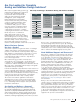
Are You Looking for Complete Analog and Interface Design Solutions? Microchip’s integrated analog technology, peripherals and features are engineered to meet today’s demanding design requirements. Our broad spectrum of analog products addresses thermal management, power management, battery management, mixed-signal, linear, interface and safety and security solutions.
THERMAL MANAGEMENT 4 THERMAL MANAGEMENT: Temperature Sensors Analog and Interface Product Selector Guide Part # Typical Accuracy (°C) Maximum Accuracy @ 25°C (°C) Logic Output Temperature Sensors TC6501 ±0.5 ±3 TC6502 ±0.5 ±3 TC6503 ±0.5 ±3 TC6504 ±0.5 ±3 TC620 ±1 ±3 TC621 Note 1 Note 1 TC622 ±1 ±5 TC623 ±1 ±3 TC624 ±1 ±5 MCP9501 ±1 ±4 MCP9502 ±1 ±4 MCP9503 ±1 ±4 MCP9504 ±1 ±4 MCP9509 ±0.5 NS MCP9510 ±0.
THERMAL MANAGEMENT PRODUCTS: Temperature Sensors (Continued) # of Remote Typical Maximum Maximum Temp. Accuracy Accuracy Temperature Sensors (°C) @ 25°C (°C) Range (°C) Serial Output Temperature Sensors with Remote Diode Monitors MIC184 1 ±1.0 ±2.0 −55 to +125 MIC280 1 ±1.0 ±2.0 −55 to +125 MIC281 1 ±1.0 ±3.0 −55 to +125 MIC284 1 ±1.0 ±2.0 −55 to +125 MIC384 2 ±1.0 ±2.0 −55 to +125 MCP9902 1 ±0.25 ±1.0 −40 to +125 MCP9903 2 ±0.25 ±1.0 −40 to +125 MCP9904 3 ±0.25 ±1.0 −40 to +125 EMC1033 2 ±1.
THERMAL MANAGEMENT: Sensor Conditioning ICs 6 Part # Analog and Interface Product Selector Guide Typical Tc Accuracy Typical Th Accuracy 1 1 MCP9600 Maximum Temperature Range (°C) −40 to +125 Vcc Range (V) +2.7 to +5.5 Maximum Supply Current (µA) 500 Features Packages Fully integrated thermocouple EMF to temperature converter. Supports thermocouple K, J, T, N, S, E B and R.
THERMAL MANAGEMENT: Closed-Loop Fan Controllers with SMBus/I2C Interface (Continued) Part # # of Fan Drivers PWM/Linear Control # of Remote Temp. Monitors Ambient Temp. Sensor Typical Accuracy (°C) Maximum Accuracy @ 25°C (°C) Maximum Temperature Range (°C) Vcc Range (V) SMBus Alert System Shutdown Voltage Monitors Description EMC2106 2 PWM and Linear 4 1 ±0.25 ±1.0 −40 to +85 +3.3 and +5.
POWER MANAGEMENT 8 POWER MANAGEMENT: Voltage References Analog and Interface Product Selector Guide Vin Max (V) Part # MCP1501 5.5 MCP1525 MCP1541 LM4040C LM4040D LM4041C LM4041D MIC40403 5.5 5.5 15 15 15 15 10 Output Voltage (V) 1.024, 1.250, 1.8, 2.048, 2.5, 3.0, 3.3, 4.096 2.5 4.096 2.5, 4.096, 5.0 2.5, 4.096, 5.0 1.225, Adj. (1.24–10V) 1.225, Adj. (1.24–10V) Adjustable Max. Load Current (mA) Initial Accuracy (max.%) Temperature Coefficient (ppm/°C) Maximum Supply Current (µA @ 25°C) 20 ±0.
POWER MANAGEMENT: Single Output Linear Regulators (Continued) Output Current (mA) Vin Min (V) Vin Max (V) Vout (V) Voltage Drop Typical (mV) TC1224 100 2.7 6 2.5, 2.7, 2.8, 3.0, 3.3, 3.6, 4.0, 5.0 180 50 μA ±0.5 64 Low Droput 5-pin SOT-23 TC2015 100 2.7 6 1.8, 2.7, 2.8, 3.0, 3.3 90 55 μA ±0.4 55 Low Droput 5-pin SOT-23 TC2055 100 2.7 6 1.8, 2.7, 2.8, 3.0, 3.3 90 55 μA ±0.4 50 Low Droput 5-pin SOT-23 TC59 100 – −10 −8 380 3 μA ±0.
POWER MANAGEMENT: Single Output Linear Regulators (Continued) Part # Analog and Interface Product Selector Guide Output Current (mA) Vin Min (V) Vin Max (V) Vout (V) Voltage Drop Typical (mV) IGND Typical (μA) Output Accuracy (%) PSRR 1 kHz (dB) Features Packages MIC5377 150 2.5 5.5 Adj. 120 29 μA ±2 60 Low Dropout 5-pin SC70, 8-pin UQFN MIC5378 150 2.5 5.5 Adj. 120 29 μA ±2 60 Low Dropout 5-pin SC70, 8-pin UQFN MCP1711 150 1.4 6 1.1–5.0 670 0.
POWER MANAGEMENT: Single Output Linear Regulators (Continued) Part # MCP1755 Output Current (mA) Vin Min (V) Vin Max (V) Vout (V) Voltage Drop Typical (mV) IGND Typical (μA) Output Accuracy (%) PSRR 1 kHz (dB) 300 3.6 16 1.8–5.5 300 68 μA ±0.85 80 Features High Input, Low Dropout Packages 3-pin SOT-223, 8-pin DFN, 5-pin SOT-223, 5-pin SOT-23 MCP1755S 300 3.6 16 1.8–5.5 300 68 μA ±0.85 80 Low Dropout 3-pin SOT-223, 8-pin DFN MCP1824 300 2.1 6 0.8, 1.2, 1.8, 2.5, 3.0, 3.3, 5.
POWER MANAGEMENT: Single Output Linear Regulators (Continued) Part # Analog and Interface Product Selector Guide TC1264 Output Current (mA) Vin Min (V) Vin mAx (V) Vout (V) Voltage Drop Typical (mV) IGND Typical (μA) Output Accuracy (%) PSRR 1 kHz (dB) 800 2.7 6 1.8, 2.5, 3.0, 3.3 450 80 μA ±0.5 64 Features Packages Low Dropout 3-pin TO-220, 3-pin SOT-223 3-pin DDPAK 5-pin TO-220, 5-pin DDPAK, 8-pin SOIC 150mil TC1265 800 2.7 6 1.8, 2.5, 3.0, 3.3 450 80 μA ±0.
POWER MANAGEMENT: Single Output Linear Regulators (Continued) Part # Output Current (mA) Vin Min (V) Vin mAx (V) Vout (V) Voltage Drop Typical (mV) IGND Typical (μA) Output Accuracy (%) PSRR 1 kHz (dB) Features Packages MIC29300 3000 2.25 26 3.3, 5.0, 12 370 37 mA ±1 – Load Dump, Reverse Current Protection 3-pin TO-263, 3-pin TO-220 MIC29301 3000 2.25 26 3.3, 5.0, 12 370 37 mA ±1 – Load Dump, Reverse Current Protection 5-pin TO-220, 5-pin DDPAK MIC29302 3000 2.25 26 Adj.
POWER MANAGEMENT: Multiple Output Linear Regulators Part # Product Type Iout #1 Iout #2 Iout #3 Iout #4 Vin Min. (V) Vin Max. (V) Vout (V) Analog and Interface Product Selector Guide Voltage Drop Typ. (mV) IGND Typ. (μA) PSRR 1kHz (dB) Packages MIC2210 Dual LDOs 150 mA 300 mA – – 2.25 5.5 Please Refer to Datasheet 120/140 48/60 μA 60 10-pin VDFN MIC2211 Dual LDOs 150 mA 300 mA – – 2.25 5.
POWER MANAGEMENT: Multiple Output Linear Regulators (Continued) Part # Product Type Iout #1 Iout #2 Iout #3 Iout #4 Vin Min. (V) Vin Max. (V) Voltage Drop Typ. (mV) Vout (V) IGND Typ. (μA) PSRR 1kHz (dB) Packages MIC5389 Dual LDOs 200 mA 200 mA – – 2.5 5.5 Please Refer to Datasheet 175 32 μA 73 6-pin WLCSP MIC5392 Dual LDOs 150 mA 150 mA – – 2.5 5.5 Please Refer to Datasheet 155 57 μA 60 6-pin UDFN, 6-pin X2DFN MIC5393 Dual LDOs 150 mA 150 mA – – 2.5 5.
POWER MANAGEMENT: Single Output Switching Regulators (Buck) Analog and Interface Product Selector Guide MCP1601 MCP1602 MCP1603 Input Voltage Range (V) 2.7 to 5.5 2.7 to 5.5 2.7 to 5.5 Output Voltage (V) 0.9V to Vin 0.8 to 4.5 0.8 to 4.0 Operating Junction Temperature Range (°C) −40 to +85 −40 to +85 −40 to +85 Switching Frequency (kHz) 750 2000 2000 Output Current (mA) 500 500 500 MCP1612 2.7 to 5.5 0.8 to 5.
POWER MANAGEMENT: Single Output Switching Regulators (Boost) (Continued) Input Voltage Range (V) 2.2 to 16 2.4 to 16 Output Voltage (V) Up to 22 Up to 16 Operating Junction Temperature Range (°C) −40 to +125 −40 to +125 Switching Frequency (kHz) 1200 1200 Output Current (mA) 350 750 MIC2605/06 3 to 40 Up to 65 −40 to +125 1200/2000 800 MIC2145 MIC2570/1 MIC2288 MIC3172 MIC2295/96 MIC2601/02 MIC2250/51 MIC2172 MIC2253 MIC2171 MIC2875/76 2.5 to 5.5 2.5 to 10 2.5 to 10 2.5 to 10 2.5 to 10 0.
POWER MANAGEMENT: Multiple Output Switching Regulators (Continued) Analog and Interface Product Selector Guide MIC2225 MIC23060 MIC2800 MIC2810 MIC2811 MIC2821 MIC2826 MIC2827 Operating Temperature Range (°C) Description Input Voltage Range (V) Number of Outputs 2 MHz DC/DC Converter with LDO 2.7 to 5.5 2 2.7 to 5.5 2 2.7 to 5.5 3 DC/DC: 1.8 to 3.3 LDOs: 0.8 to 3.6 −40 to +125 PWM Mode 2.7 to 5.5 3 DC/DC: 1.8 to 3.3 LDOs: 0.8 to 3.6 −40 to +125 PWM Mode 2.7 to 5.5 4 2.7 to 5.
POWER MANAGEMENT: PWM Controllers Part # Supported Topologies Supported Outputs Input Voltage Range (V) Output Voltage (V) Operating Frequency (Hz) Operating Temp.
POWER MANAGEMENT: PWM Controllers (Continued) Analog and Interface Product Selector Guide Forward, Flyback Forward, Flyback Flyback, Boost, SEPIC, Ćuk Flyback, Boost, SEPIC, Ćuk Flyback, Boost, SEPIC, Ćuk Flyback, Boost, SEPIC, Ćuk Flyback, Boost, SEPIC, Ćuk Flyback, Boost, SEPIC, Ćuk Supported Outputs 1 1 1 1 1 1 1 1 Input Voltage Range (V) 9.0 to 180 9.0 to 180 3.0 to 5.5 3.0 to 5.5 3.0 to 5.5 3.0 to 5.5 3.5 to 16 3.5 to 16 Output Voltage (V) – – – – – – – – Operating Frequency (Hz) Adj.
POWER MANAGEMENT: Power Modules Part # Input Voltage Range (V) Output Voltage (V) Operating Temp. Range (°C) Control Scheme MIC28304-1 MIC28304-2 MIC45205-1 MIC45205-2 MIC45208-1 MIC45208-2 MIC45212-1 MIC45212-2 MIC33030 MIC33050 MIC33153 MIC3385 MIC28303-1 MIC28303-2 MIC45116-1 MIC45116-2 MIC45404 4.5 to 70 4.5 to 70 4.5 to 26 4.5 to 26 4.5 to 26 4.5 to 26 4.5 to 26 4.5 to 26 2.7 to 5.5 2.7 to 5.5 2.7 to 5.5 2.7 to 5.5 4.5 to 50 4.5 to 50 4.5 to 20 4.5 to 20 4.5 to 19 Adj. Adj. Adj. Adj. Adj. Adj.
POWER MANAGEMENT: CPU/System Supervisors Analog and Interface Product Selector Guide – – Operating Temp. Range (°C) −40 to +85 −40 to +85 Vcc Range (V) 1.0–5.5 1.0–5.5 Push-Pull Push-Pull Typical Reset Pulse Width (ms) 350 350 Typical Supply Current (μA) 45 45 – – −40 to +125 1.0–5.5 Active Low Push-Pull 120 1 – – – −40 to +125 1.0–5.5 Active Low Push-Pull 120 1 Supervisor – – – −40 to +85 2.7, 3, 3.15, 4.5, 4.6, 4.75, 4.
POWER MANAGEMENT: CPU/System Supervisors (Continued) Type Watchdog Timer Manual Reset Power Fail Operating Temp. Range (°C) Vcc Range (V) Nominal Reset Voltage (V) MIC810 Supervisor – – – −40 to +85 1.4–5.5 2.63, 2.93, 3.08, 4.00, 4.38, 4.63 MIC811 Supervisor – ü – −40 to +85 1.4–5.5 2.63, 2.93, 3.08, 4.00, 4.38, 4.63 MIC812 Supervisor – ü – −40 to +85 1.4–5.5 2.63, 2.93, 3.08, 4.00, 4.38, 4.63 MIC1810 MIC1815 Supervisor Supervisor – – – – – – −40 to +85 −40 to +85 1.
POWER MANAGEMENT: Power MOSFET Drivers Analog and Interface Product Selector Guide Peak Output Current (source/sink, A) Maximum Supply Voltage (V) Output Resistance (source/sink, Ω) Propagation Delay (Td1/Td2, ns) Rise/Fall Time (Tr/Tf, ns) Capacitive Load Drive Low-Side Power MOSFET Drivers MCP1401 Single Inverting MCP14A0051 Single Inverting MCP14A0052 Single Non-inverting MCP1402 Single Non-inverting TC1410N Single Non-inverting TC1411N Single Non-inverting MIC4416 Single Non-Inverting MIC441
POWER MANAGEMENT: Power MOSFET Drivers (Continued) Peak Output Current (source/sink, A) Maximum Supply Voltage (V) Output Resistance (source/sink, Ω) Propagation Delay (Td1/Td2, ns) Rise/Fall Time (Tr/Tf, ns) Capacitive Load Drive Low-Side Power MOSFET Drivers (Continued) MCP14E8 Dual Complimentary TC1412 Single Inverting TC1412N Single Non-Inverting MIC4478 Dual Non-Inverting MIC4479 Dual Inverting MIC4480 Dual Complimentary TC4423A Dual Inverting TC4424A Dual Non-Inverting TC4425A Dual Complimentary
POWER MANAGEMENT: Power MOSFET Drivers (Continued) Part # Drivers Analog and Interface Product Selector Guide High-Side Power MOSFET Drivers TC4431 High-Side Single TC4432 High-Side Single TC4403 Floating Load Driver High-Side or Low MIC5011 Side Single High-Side or Low MIC5013 Side Single High-Side or Low MIC5014 Side Single High-Side or Low MIC5015 Side Single High-Side or Low MIC5018 Side Single High-Side or Low MIC5019 Side Single Configuration Peak Output Current (source/sink, A) Maximum Supp
POWER MANAGEMENT: Power MOSFETs Vds (V) Configuration Polarity Rds (on) @ 4.5V (mΩ, Max.) Rds (on) @ 10V (mΩ, Max.) Qg @ 4.5V (nC, Max.) Id (A, Max. @ 25°C, Tcase) Vgs (th) (V, Min.) Qgd (nC, Typ.) Rg (Ω, Typ.) MCP87018 25 Single N 2.2 1.9 37 100 1 13 1.5 8-pin 5 × 6 PDFN MCP87022 25 Single N 2.6 2.3 29 100 1 9 1.3 8-pin 5 × 6 PDFN MCP87030 25 Single N 4 3.5 22 100 1 6.7 1.2 8-pin 5 × 6 PDFN MCP87050 25 Single N 6 5 15 100 1 4.7 1.
POWER MANAGEMENT: Hot Swap Controllers Part # Analog and Interface Product Selector Guide Number of Outputs Vpos to Vneg Differential Voltage (V) Junction Temperature Range (°C) OVLO UVLO Power Good Int/Ext FET 1 −0.3 to +15.0 −40 to +85 Adjustable Adjustable Adjustable Ext MCP18480 Applications Packages −48V Telecom/Datacom, Bus/Backplane 20-pin SSOP POWER MANAGEMENT: Power Switches Part # Description USB Port Power Switch (55 mΩ) High-Speed USB 2.
POWER MANAGEMENT: Power Switches (Continued) Part # Channels Vin Range (V) Fixed Current Limit (Min.) Adj. Current Limit (Max.) Rds(on) (mΩ) Current Limited/ Latched Reverse Blocking Enable Logic ULVO Thermal Protection Fault Flag Current Measurement Packages Current Limit USB Protection Switches (Continued) MIC2026A-1 Dual 2.7–5.5 500 mA – 100 ü ü Active High ü ü ü – 8-pin SOIC MIC2026A-2 Dual 2.7–5.
POWER MANAGEMENT: Power Switches (Continued) Part # Channels Vin Range (V) Analog and Interface Product Selector Guide Fixed Current Limit (Min.) Adj. Current Limit (Max.) Rds(on) (mΩ) Current Limited/ Latched Reverse Blocking Enable Logic ULVO Thermal Protection Fault Flag Current Measurement Packages Current Limit USB Protection Switches (Continued) MIC2506 MIC2544-1 Dual 2.7–7.5 1.0A – 75 ü ü Active High – ü ü – 8-pin SOIC, 8-pin PDIP Single 2.7–5.5 – 1.
POWER MANAGEMENT: Power Switches (Continued) Part # Channels Vin Range (V) Max. Switch Current Rds(on) (mΩ) Soft Start (μs) Load Discharge (Ω) Enable Logic Input Pull-Up Resistor Reverse Blocking Packages MIC94063 Single 1.7–5.5 2.0 77 800 200 Active High – – 6-pin SC70, 1.2 × 1.6 MIC94064 Single 1.7–5.5 2.0 77 115 – Active High – – 6-pin SC70, 1.2 × 1.6 MIC94065 Single 1.7–5.5 2.0 77 115 200 Active High – – 6-pin SC70, 1.2 × 1.6 MIC94070 Single 1.7–5.5 1.
DISPLAY AND LED DRIVERS DISPLAY AND LED DRIVERS: Electroluminescent Backlight Drivers Analog and Interface Product Selector Guide Part # Type Input Voltage Low (V) Input Voltage High (V) Nominal Output Voltage (V) Max. Switch Resistance (Ω) Output Regulation Max. Lamp Size per Device (in2) Packages 16-Segment Drivers HV509 16-Segment Drivers 2 5.5 ±50 to ±200 – – 6.5 32-pin VQFN HV528 16-Segment Drivers 1.7 5.5 ±50 to ±200 – – 6.
DISPLAY AND LED DRIVERS: LED Drivers (Continued) Part # Topology Input Voltage (V) Dimming Iq Typ. (mA) Switching Frequency (Hz) Switching MOSFET Dithered ILED Accuracy Vfb (V) Packages General Purpose LED Drivers (Continued) HV9910C Buck 15–450 PWM/Linear 1.0 100K External FET – ±5% 0.25 16-pin SOIC 150 mil, 8-pin SOIC 150 mil HV9918 Buck 4.5–40 PWM 1.5 2M 0.7A FET – ±5% 0.23 8-pin WDFN HV9919B Buck 4.5–40 PWM 1.5 2M External FET – ±5% 0.
DISPLAY AND LED DRIVERS: LED Drivers (Continued) Part # Input Voltage (V) # of White LEDs Dimming Iq Typ. (mA) V Dropout LED @ 20 mA ILED Matching Ext. LDOs Vdropout IQLDO Comments Packages Analog and Interface Product Selector Guide Linear LED Drivers MIC2841A 3–5.5 4 @ 20 mA PWM (200 Hz–500 kHz) 1.4 40 mV ±1.5% – – – DAM™ 10-pin UDFN MIC2842A 3–5.5 4 @ 20 mA 1-Wire, 48-Steps 1.4 40 mV ±1.5% – – – DAM 10-pin UDFN MIC2843A 3–5.5 6 @ 20 mA PWM (200 Hz–500 kHz) 1.
HIGH-VOLTAGE INTERFACE HIGH-VOLTAGE INTERFACE: Driver Arrays Part # Sink HV5122 HV5222 HV5522 HV5523 HV5530 HV5622 HV5623 HV5630 MIC5800 MIC5801 MIC5821 MIC5822 MIC5841 Output Channels Vout Operating (V) Transient Vout Operating (V) Sustained Input Structure 32 250 225 Serial Serial to parallel converter with output enable and strobe 32 250 225 Serial Serial to parallel converter with output enable and strobe 32 230 220 Serial Serial to parallel converter with latches, polarity, and blank
HIGH-VOLTAGE INTERFACE: Amplifiers and MEMS Drivers Part # Analog and Interface Product Selector Guide HV254 Output Channels Slew Rate (V/μs) Closed Loop Gain (V/V) Feedback Resistance (MΩ) Source Current (Max. μA) Sink Current (Max. μA) Output Capacitive Load (Max. pF) 32 3 50 12 300 300 100 Packages 100-pin MQFP HV256 32 2 72 12 715 715 3000 100-pin MQFP HV257 32 2 72 12 500 500 3000 100-pin MQFP HV264 4 9 66.7 5.
HIGH-VOLTAGE INTERFACE: MOSFETs – Interface (Continued) Part # BVdss Min. (V) Enhancement-Mode N-Channel (Continued) 2N7000 2N7002 2N7008 VN2222L VN0808 VN0109 2N6661 VN2210 TN0610 TN2510 TN0110 VN2110 VN1206 TN0620 VN2224 TN2524 VN2406 VN2410 TN2124 TN2425 TN5325 TN2130 TN2435 TN5335 TN2640 TN2540 VN4012 VN2450 VN0550 VN2460 Rds(on) Max. (Ω) Ciss Max. (pF) Vgs(th) Max. (V) 60 60 60 60 80 90 90 100 100 100 100 100 120 200 240 240 240 240 240 250 250 300 350 350 400 400 400 500 500 600 5.0 7.5 7.5 7.
HIGH-VOLTAGE INTERFACE: MOSFETs – Interface (Continued) Part # BVdss Min. (V) Analog and Interface Product Selector Guide Rds(on) Max. (Ω) Ciss Typ. (pF) Vgs(th) Max. (V) 15.0 25.0 30.0 15.0 25.0 30.0 125.0 2.5 1.3 1.2 0.8 1.0 2.0 3.0 0.3 1.5 2.5 3.0 3.0 3.0 3.0 4.0 5.0 7.5 7.5 7.5 4.0 3.0 4.0 0.4 300 125 110 300 125 190 70 110 200 190 190 125 70 65 300 150 50 50 60 65 50 50 60 50 50 60 50 65 50 500 −2.0 −2.4 −2.4 −2.0 −2.4 −3.5 −4.5 1.0 1.0 2.5 1.6 1.6 1.6 2.4 2.4 2.0 2.0 2.0 2.0 2.4 2.0 2.4 3.
HIGH-VOLTAGE INTERFACE: Application Specific (Continued) Part # # of Channels Input Voltage Low (V) Input Voltage High (V) Output Voltage Low (V) Output Voltage High (V) Input to Output Isolation (V) Packages Complimentary MOSFET Level Translator and Driver HT0440 2 3.15 5.5 6 10 ±400 10-pin VDFN, 8-pin SOIC 150 mil HT0740 1 3.15 5.5 4.5 8.5 ±400 8-pin SOIC 150 mil High-Side Current Monitor Vin (V) Gain Rise and Fall Time (μs) Vsense Max. (mV) Quiescent Current Max.
LINEAR: Op Amps (Continued) Analog and Interface Product Selector Guide 190 kHz 190 kHz 190 kHz 190 kHz Iq Typical (µA) 19 19 19 19 Vos Max (mV) 0.15 0.15 0.15 0.15 Typical Input Bias Current (pA) 15000 15000 15000 15000 Input Voltage Noise Density (nV/rtHz) 32(1) 32(1) 32(1) 32(1) 1 300 kHz 20 5 1 52(1) 1.8 to 6.
LINEAR: Op Amps (Continued) 4 4 7 Typical Input Bias Current (pA) 1 1 50000 Input Voltage Noise Density (nV/rtHz) 19(2) 19(2) – 480 4 10 28(1) 2.7 MHz 480 4 10 28 4 2.7 MHz 480 4 10 28(1) 1 2 1 4 1 2 4 2 1 1 1 2 4 1 2 1 4 2.8 MHz 2.8 MHz 2.8 MHz 2.8 MHz 2.8 MHz 2.8 MHz 2.8 MHz 3.0 MHz 3.5 MHz 4.0 MHz 4 MHz 4 MHz 4 MHz 5 MHz 5 MHz 5 MHz 5 MHz 230 230 230 230 200 200 200 31 540 33 240 240 240 445 445 445 445 2 2 2 2 3 3 3 6 1.5 20 1.5 1.5 1.
LINEAR: Op Amps (Continued) Analog and Interface Product Selector Guide # per Package GBWP Iq Typical (µA) Vos Max (mV) Typical Input Bias Current (pA) Input Voltage Noise Density (nV/rtHz) MCP6H92 2 10 MHz 2000 4 10 23(1) MCP6H94 4 10 MHz 2000 4 10 23(1) MCP6L91 MCP6L92 MCP6L94 1 2 4 10 MHz 10 MHz 10 MHz 850 850 850 4 4 4 1 1 1 MCP621 1 20 MHz 2500 0.2 MCP621S MCP622 1 2 20 MHz 20 MHz 2500 2500 0.2 0.
LINEAR: Zero-Drift Operational Amplifiers Part # # per Package GBWP Iq Max (mA) Vos Max (µV) Vos Drift Max (µV/°C) Operating Voltage (V) Temperature Range (°C) 1 2 4 1 2 4 1 1 2 4 1 2 1 1 2 1 2 1 1 2 1 1 2 4 1 2 4 1 2 4 80 kHz 80 kHz 80 kHz 300 kHz 300 kHz 300 kHz 0.4 MHz 1 MHz 1 MHz 1 MHz 1.3 MHz 1.3 MHz 1.3 MHz 1.3 MHz 1.3 MHz 1.3 MHz 1.5 MHz 2 MHz 2 MHz 2 MHz 2 MHz 2 MHz 2 MHz 2 MHz 5 MHz 5 MHz 5 MHz 10 MHz 10 MHz 10 MHz 0.011 0.011 0.011 0.034 0.034 0.034 3 0.13 0.13 0.13 0.4 0.4 0.4 0.4 0.
LINEAR: Instrumentation Amplifiers Analog and Interface Product Selector Guide # Per Package Bandwidth (kHz) Iq Max (mA) Max Vos (µV) Vos Drift Max (µV/°C) Operating Voltage (V) Temperature Range (°C) Features MCP6N11 Part # 1 500 1.1 350 2.7 1.8 to 5.5 −40 to +125 MCP6N16 1 500 1.6 17 0.06 1.8 to 5.
MIXED SIGNAL: Delta-Sigma A/D Converters Part # MCP3421 MCP3422 MCP3423 MCP3424 MCP3425 MCP3426 MCP3427 MCP3428 MCP3550-50 MCP3550-60 MCP3551 MCP3553 Resolution (bits) 18 to 12 18 to 12 18 to 12 18 to 12 16 to 12 16 to 12 16 to 12 16 to 12 22 22 22 20 Maximum Sampling Rate (samples/sec) 4 to 240 4 to 240 4 to 240 4 to 240 15 to 240 15 to 240 15 to 240 15 to 240 13 15 14 60 # of Input Channels 1 Diff 2 Diff 2 Diff 4 Diff 1 Diff 2 Diff 2 Diff 4 Diff 1 Diff 1 Diff 1 Diff 1 Diff Interface IC I2C I2C I 2C I
MIXED SIGNAL: Energy Measurement AFEs Dynamic Range Part # Typical Accuracy ADC Channels ADC Resolution Gain Selection SINAD Output Type Temperature Range (°C) Vdd (V) Analog and Interface Product Selector Guide MCP3918/10 10000:1 0.1% 1/2 24-bit 93.5 Up to 32 SPI/2-wire 2.7 to 3.6 −40 to +125 MCP3919 10000:1 0.1% 3 24-bit 93.5 Up to 32 SPI/2-wire 2.7 to 3.6 −40 to +125 MCP3912 10000:1 0.1% 4 24-bit 93.5 Up to 32 SPI 2.7 to 3.6 −40 to +125 MCP3913/14 10000:1 0.
MIXED SIGNAL: Display A/D Converters Display Type LCD LCD LED LED LCD LCD LED LED LCD LCD LCD Part # TC7106 TC7106A TC7107 TC7107A TC7116 TC7116A TC7117 TC7117A TC7126 TC7126A TC7129 Supply Voltage (V) 9 9 ±5 ±5 9 9 ±5 ±5 9 9 9 Resolution (Digits) 3½ 3½ 3½ 3½ 3½ 3½ 3½ 3½ 3½ 3½ 4½ Resolution (Counts) ±2,000 ±2,000 ±2,000 ±2,000 ±2,000 ±2,000 ±2,000 ±2,000 ±2,000 ±2,000 ±20,000 Power (mW) 10 10 10 10 10 10 10 10 0.5 0.5 4.
MIXED SIGNAL: Digital Potentiometers (Continued) Analog and Interface Product Selector Guide Part # # of Taps Memory # Per Package Interface Resistance (kOhms) INL (Max) DNL (Max) Temperature Range (°C) MCP4261 256 Nonvolatile 2 SPI 5, 10, 50, 100 1 0.
MIXED SIGNAL: D/A Converters (Continued) Part # MCP47FEB11 MCP47FEB21 MCP47FEB02 MCP47FEB12 MCP47FEB22 MCP47FVB01 MCP47FVB11 MCP47FVB21 MCP47FVB02 MCP47FVB12 MCP47FVB22 MCP47DA1 MCP4706 MCP4716 MCP4726 MCP4725 MCP4728 MCP4801 MCP4811 MCP4821 MCP4802 MCP4812 MCP4822 MCP4901 MCP4911 MCP4921 MCP4902 MCP4912 MCP4922 Resolution (Bits) 10 12 8 10 12 8 10 12 8 10 12 6 8 10 12 12 12 8 10 12 8 10 12 8 10 12 8 10 12 DAC Channels 1 1 2 2 2 1 1 1 2 2 2 1 1 1 1 1 4 1 1 1 2 2 2 1 1 1 2 2 2 Interface Memory Voltage R
INTERFACE AND NETWORKING: LIN Transceiver Products Analog and Interface Product Selector Guide Part # Description Vreg Output Voltage (V) Operating Temp.
INTERFACE AND NETWORKING: Ethernet Products Interface (Upstream) 1588-2008 Cable Diagnostics 100 FX (Fiber Support) SPI/SQI™/8/16/32 Host Bus Clock Synchronization ü ü 64-pin QFN, 64-pin TQFP-EP 3-Port 10/100 Managed Ethernet Switch 3-Port 10/100 Managed Ethernet Switch MII/RMII/Turbo MII MII/RMII/Turbo MII – – – – – – 56-pin QFN 72-pin QFN LAN9353 3-Port 10/100 Managed Ethernet Switch with Single MII/RMII/Turbo MII or Dual RMII MII/RMII/Turbo MII ü ü ü 64-pin QFN, 64-pin TQFP-EP LAN93
INTERFACE AND NETWORKING: Wi-Fi® Modules Part # Analog and Interface Product Selector Guide Frequency Sensitivity Power Pin Range Output Count Antenna (dBm) (GHz) (dBm) Radio Power Consumption (mA) Tx Rx 245 64 (+18 dBm) Sleep MAC 12 μA Yes RN1810 802.11 b/g 37 PCB, W.FL 2.412– 2.472 −94 0 to +12 RN1723 802.11 b/g 49 RF PAD 2.412– 2.484 −83 0 to +12 120 (0 dBm) 40 4 μA Yes RN171 802.11 b/g 49 RF PAD 2.412– 2.484 −83 0 to +12 190 (+12 dBm) 38 4 μA Yes RN131 802.
INTERFACE AND NETWORKING: Bluetooth® Modules (Continued) Bluetooth Spec Module Type No Shield Option BM78 4.2 Data, DualMode Yes RN41 2.1 Data No −80 15 RN41XV 2.1 Data No −80 15 RN42 2.1 Data No −80 4 RN42XV 2.1 Data No −80 4 Product Output Rx Sensitivity (dBm) Power (dBm) (typ.) −90 (BR/EDR) 2 −92 LE Packages (Dimensions) 22 × 12 × 2.4 mm 25 × 12 × 1.
INTERFACE AND NETWORKING: USB Bridge Devices Analog and Interface Product Selector Guide Part # USB Speed USB Compliant PHY MCU Interface Tx/Rx Buffer Size (bytes) Number of GPIO Operating Voltage (V) MCP2200 Full-Speed USB (12 Mb/s), Low-Speed USB (1.5 Mb/s) Yes Yes UART 128/128 8 2.7 to 5.5 20-pin SOIC, 20-pin TSSOP, 20-pin QFN Packages MCP2210 Full-Speed USB (12 Mb/s), Low-Speed USB (1.5 Mb/s) Yes Yes SPI 64 9 3.3 to 5.
INTERFACE AND NETWORKING: Real-Time Clock/Calendar (RTCC) SPI I2C Bus Timing Features Product Pins MCP7940M MCP7940N MCP7940X MCP7941X MCP7951X MCP7952X 8 8 8 8 10 10 Digital Trimming (Adj./Range) ±127 ppm ±127 ppm ±127 ppm ±127 ppm ±255 ppm ±255 ppm Alarm Settings 1 sec. 1 sec. 1 sec. 1 sec. 0.01 sec. 0.01 sec. MCP795W1X 14 ±255 ppm 0.01 sec. ü MCP795W2X 14 ±255 ppm 0.01 sec. ü Power Memory(1) WDT Outputs – – – – – – 1. 3. 1. 3.
CO AND SMOKE DETECTOR ICS: CO Detectors Analog and Interface Product Selector Guide Part # Operating Voltage (Vdc) Voltage Regulator (Vdc) LED Driver Horn Driver Interconnect RE46C800 2 to 12 3.3 Yes Yes Yes Low Battery Detection Yes Brown Out Boost Regulator Yes Yes Op Amp Vos Max (µV) 1000 Op Amp lb Max (pA) 200 Op Amp GBWP (kHz) 10 Op Amp Aol (dB) 115 Op Amp Slew Rate (V/µS) 0.
ULTRASOUND: Ultrasound MOSFET Drivers MD1210 MD1211 MD1213 # of Channels 2 2 2 Input Voltage Min. (V) 1.2 1.8 1.8 Input Voltage Max. (V) 5.0 5.0 5.0 Ouput Voltage Bipolar (V) NA NA ±5 Output Voltage Unipolar (V) 0–12 0–12 0–12 Output Rise/ Fall Time 6 ns/6 ns 10 ns/10 ns 6 ns/6 ns Peak Current ±2A ±2A ±2A MD1711 12 1.8 3.
Featured Analog Development Tools For a complete list of development tools, please visit www.microchip.com/development tools. Thermal Management Products Linear Products MCP9600 Evaluation Board (ADM00665) MCP6V01 Thermocouple Auto-Zeroed Reference Design Board (MCP6V01RD-TCPL) The MCP9600 Evaluation Board is used to digitize the Thermocouple EMF voltage to degree Celsius with ±1 .5°C accuracy . You can easily evaluate all device features using a Type K thermocouple .
Featured Analog Development Tools For a complete list of development tools, please visit www.microchip.com/development tools. MCP39F511 Power Monitor Demonstration Board (ARM00667) UTC2000 Basic USB Type-C™ Controller Evaluation Kit (EVK-UTC2000) The MCP39F511 Power Monitor Demonstration Board is a fully functional single-phase power monitor and energy monitoring system .
Support Training Microchip is committed to supporting its customers in developing products faster and more efficiently . We maintain a worldwide network of field applications engineers and technical support ready to provide product and system assistance . In addition, the following service areas are available at www.microchip.com: ■ Support link provides a way to get questions answered fast: http://support.microchip.com ■ Sample link offers evaluation samples of any Microchip device: http://sample.