
User manual


Table Of Contents
- Introduction
- Document Layout
- Conventions Used in this Guide
- Recommended Reading
- The Microchip Web Site
- Customer Support
- Document Revision History
- Chapter 1. Product Overview
- 1.1 Introduction
- 1.2 MCP6XXX Amplifier Evaluation Board 4 Kit Contents
- 1.3 MCP6XXX Amplifier Evaluation Board 4 Description
- Chapter 2. Installation and Operation
- 2.1 Introduction
- 2.2 Required Tools
- 2.3 MCP6XXX Amplifier Evaluation Board 4 Set-up
- 2.4 MCP6XXX Amplifier Evaluation Board 4 Operation
- A.1 Introduction
- A.2 Board - Schematic
- A.3 Board - Top Silk and Metal Layers
- A.4 Board - Top Metal Layer
- A.5 Board - Bottom Metal Layer
- B.1 MCP6XXX Amplifier Evaluation Board 4 BOM
MCP6XXX Amplifier Evaluation Board 4 User’s Guide
DS51681A-page 8 © 2007 Microchip Technology Inc.
The power supply voltage needs to be in the allowed range for the installed operational
amplifiers. Any of Microchip’s op amps that operate below 5.5V can be used. Moreover,
the power supply is protected by a zener diode with nominal voltage 6.2V and
bypassed by a 1.0 µF capacitor. (See Figure 2-3: “Power Supply Block.”)
The output load consists of a capacitor (C
L
) and two resistors (R
L
, R
ISO
). R
ISO
is used
to stabilize the amplifier when it drives a large capacitive load. R
ISO
is a short circuit
(0Ω) when C
L
is small.
The non-inverting comparator provides two trip points which are at 0.8V
DD
and 0.2V
DD
.
(See Section Figure 2-4: “Non-Inverting Comparator Block.”)
The resistors that are part of an amplifier are placed in pin sockets which are labeled.
The op amps are bypassed by 0.1 µF capacitors and the single op amp U1 can have
either a PDIP-8 or SOIC-8 package.
• PDIP-8 packages are inserted into the DIP-8 socket to the right of the U1 label.
• SOIC-8 packages can be accommodated; see Section 2.4.3 “Amplifier
Modifications Using 8-Pin SOIC Op Amps”.
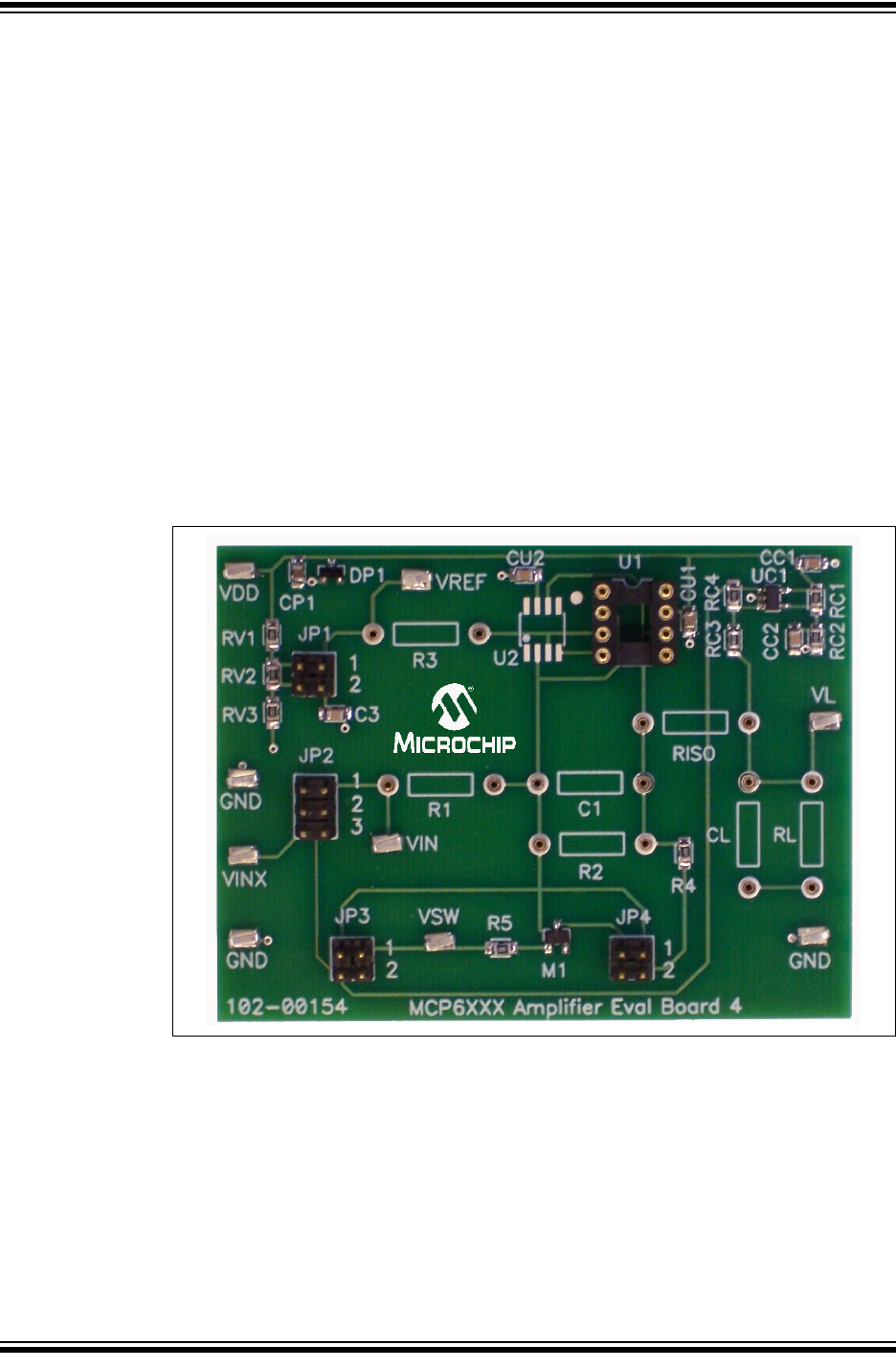
The (surface mount) test points for power supply, ground, input signal and output signal
allow lab equipment to be connected to the board. The MCP6XXX Amplifier Evaluation
Board 4 top view is shown in Figure 2-2.
FIGURE 2-2: MCP6XXX Amplifier Evaluation Board 4 Top View.