
User manual


Table Of Contents
- Introduction
- Document Layout
- Conventions Used in this Guide
- Recommended Reading
- The Microchip Web Site
- Customer Support
- Document Revision History
- Chapter 1. Product Overview
- 1.1 Introduction
- 1.2 MCP6XXX Amplifier Evaluation Board 4 Kit Contents
- 1.3 MCP6XXX Amplifier Evaluation Board 4 Description
- Chapter 2. Installation and Operation
- 2.1 Introduction
- 2.2 Required Tools
- 2.3 MCP6XXX Amplifier Evaluation Board 4 Set-up
- 2.4 MCP6XXX Amplifier Evaluation Board 4 Operation
- A.1 Introduction
- A.2 Board - Schematic
- A.3 Board - Top Silk and Metal Layers
- A.4 Board - Top Metal Layer
- A.5 Board - Bottom Metal Layer
- B.1 MCP6XXX Amplifier Evaluation Board 4 BOM
MCP6XXX Amplifier Evaluation Board 4 User’s Guide
DS51681A-page 6 © 2007 Microchip Technology Inc.
1.3 MCP6XXX AMPLIFIER EVALUATION BOARD 4 DESCRIPTION
MCP6XXX Amplifier Evaluation Board 4 is intended to support the inverting integrator
circuit.
The MCP6XXX Amplifier Evaluation Board 4 has the following features:
• All amplifier resistors and capacitors are socketed
• Supports all Microchip single op amps
- PDIP-8 package (e.g., MCP6021) are socketed
- SOIC-8 package can be accomodated; see Section 2.4.3 “Amplifier
Modifications Using 8-Pin SOIC Op Amps”
• Test points for connecting lab equipment
• Single supply configuration
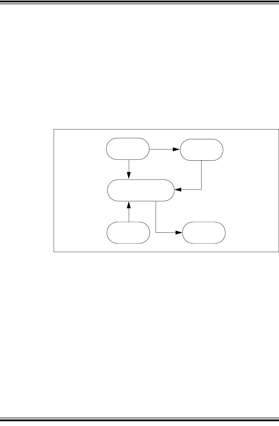
Figure 1-2 shows the block diagram of the MCP6XXX Amplifier Evaluation Board 4.
Lab equipment can be attached (via test points) to measure the amplifier response.
FIGURE 1-2: MCP6XXX Amplifier Evaluation Board 4 Block Diagram.
Amplifier
Signal Inputs
and
Tes t P oin ts
(Op Amp, Resistors and
Power Supply
and
Test Point
Signal Output
and
Test P o in ts
Non-Inverting
Comparator
Block
Capacitors)