MCP6L91/1R/2/4 10 MHz, 850 µA Op Amps Features: Description: • • • • • • • The Microchip Technology Inc. MCP6L91/1R/2/4 family of operational amplifiers (op amps) provides wide bandwidth for the current. The input bias currents and voltage ranges make it easier to fit into many applications. Available in SOT-23-5 Package Gain Bandwidth Product: 10 MHz (typical) Rail-to-Rail Input/Output Supply Voltage: 2.4V to 6.0V Supply Current: IQ = 0.
MCP6L91/1R/2/4 NOTES: DS22141B-page 2 2009-2011 Microchip Technology Inc.
MCP6L91/1R/2/4 1.0 ELECTRICAL CHARACTERISTICS 1.1 Absolute Maximum Ratings † † Notice: Stresses above those listed under “Absolute Maximum Ratings” may cause permanent damage to the device. This is a stress rating only and functional operation of the device at those or any other conditions above those indicated in the operational listings of this specification is not implied. Exposure to maximum rating conditions for extended periods may affect device reliability. VDD – VSS ............................
MCP6L91/1R/2/4 TABLE 1-2: AC ELECTRICAL SPECIFICATIONS Electrical Characteristics: Unless otherwise indicated, TA = +25°C, VDD = +5.0V, VSS = GND, VCM = VSS, VOUT VDD/2, VL = VDD/2, RL = 10 k to VL and CL = 60 pF (refer to Figure 1-1). Parameters Sym Min Typ Max Units Conditions AC Response Gain Bandwidth Product GBWP — 10 — MHz Phase Margin PM — 65 — ° Slew Rate SR — 7 — V/µs G = +1 Noise Input Noise Voltage Eni — 2.5 — Input Noise Voltage Density eni — 9.
MCP6L91/1R/2/4 2.0 TYPICAL PERFORMANCE CURVES Note: The graphs and tables provided following this note are a statistical summary based on a limited number of samples and are provided for informational purposes only. The performance characteristics listed herein are not tested or guaranteed. In some graphs or tables, the data presented may be outside the specified operating range (e.g., outside specified power supply range) and therefore outside the warranted range.
MCP6L91/1R/2/4 Note: Unless otherwise indicated, TA = +25°C, VDD = +5.0V, VSS = GND, VCM = VSS, VOUT = VDD/2, VL = VDD/2, RL = 10 kto VL and CL = 60 pF. Input Current Magnitude (A) Input, Output Voltages (V) 6 10m 1.E-02 1m 1.E-03 100µ 1.E-04 10µ 1.E-05 1µ 1.E-06 100n 1.E-07 10n 1.E-08 1n 1.E-09 100p 1.E-10 10p 1.E-11 1p 1.E-12 +125°C +85°C +25°C -40°C -1.0 -0.9 -0.8 -0.7 -0.6 -0.5 -0.4 -0.3 -0.2 -0.1 0.
MCP6L91/1R/2/4 Note: Unless otherwise indicated, TA = +25°C, VDD = +5.0V, VSS = GND, VCM = VSS, VOUT = VDD/2, VL = VDD/2, RL = 10 kto VL and CL = 60 pF. VDD – VOH IOUT 25 Slew Rate (V/µs) Ratio of Output Headroom to Output Current (mV/mA) 30 20 VOL – VSS -IOUT 15 10 5 0 100µ 1.E-04 1m 1.E-03 Output Current Magnitude (A) 10m 1.E-02 FIGURE 2-13: Ratio of Output Voltage Headroom to Output Current vs. Output Current. P-P ) 0.02 0.01 0.00 -0.01 -0.02 -0.03 -0.04 0.E+00 2.E-07 4.E-07 6.
MCP6L91/1R/2/4 NOTES: DS22141B-page 8 2009-2011 Microchip Technology Inc.
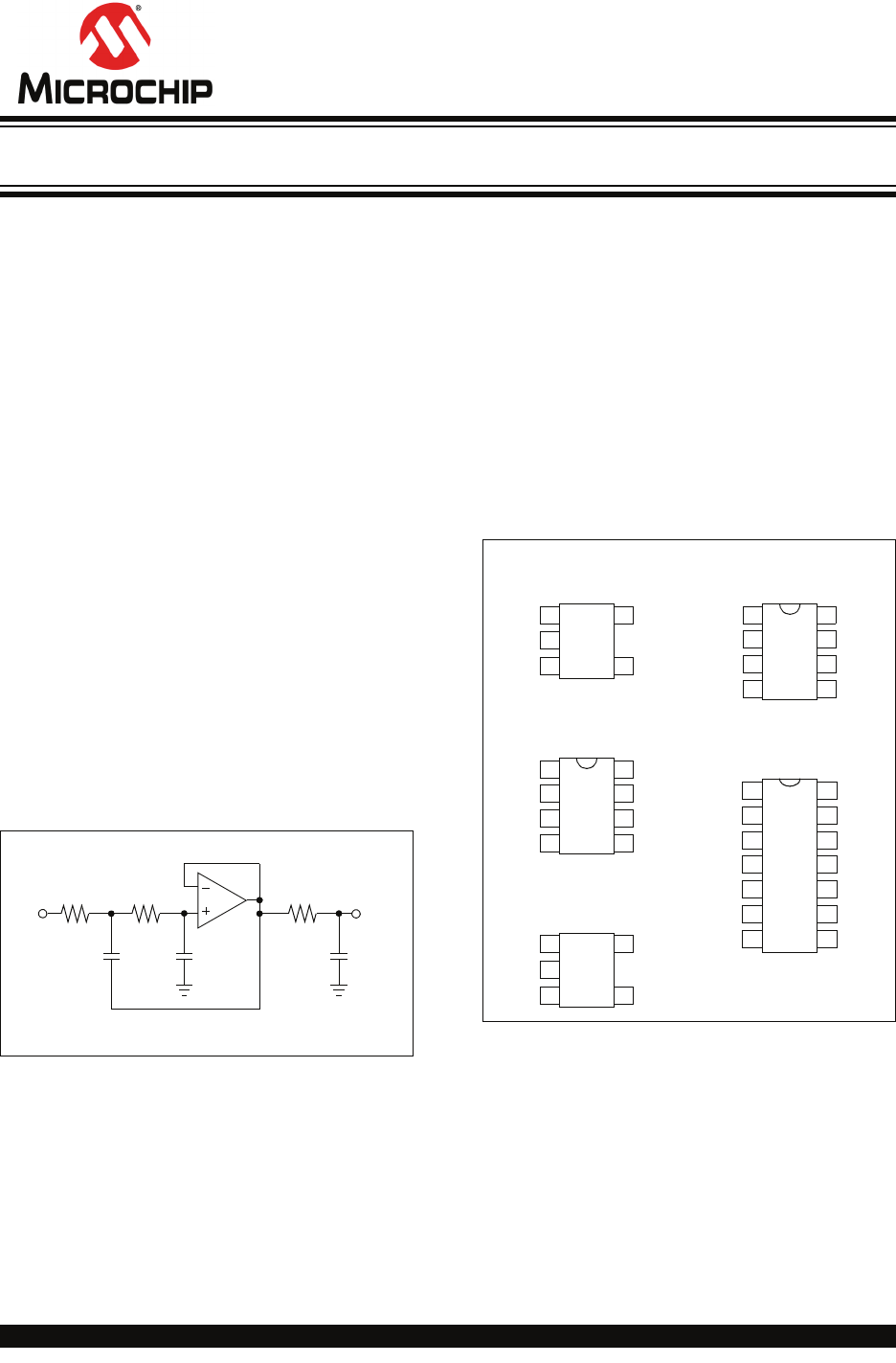
MCP6L91/1R/2/4 3.0 PIN DESCRIPTIONS Descriptions of the pins are listed in Table 3-1. TABLE 3-1: PIN FUNCTION TABLE MCP6L91 MCP6L91R MCP6L92 MCP6L94 SOT-23-5 MSOP-8, SOIC-8, SOT-23-5 MSOP-8, SOIC-8, SOIC-14, TSSOP-14 1 4 3 5 — — — — — — 2 — — — — 6 2 3 7 — — — — — — 4 — — — 1, 5, 8 1 4 3 2 — — — — — — 5 — — — — 1 2 3 8 5 6 7 — — — 4 — — — — 1 2 3 4 5 6 7 8 9 10 11 12 13 14 — 3.1 Analog Outputs The analog output pins (VOUT) are low-impedance voltage sources. 3.
MCP6L91/1R/2/4 NOTES: DS22141B-page 10 2009-2011 Microchip Technology Inc.
MCP6L91/1R/2/4 4.0 APPLICATION INFORMATION 4.1.3 NORMAL OPERATION The MCP6L91/1R/2/4 family of op amps is manufactured using Microchip’s state of the art CMOS process. It is designed for low cost, low power and general purpose applications. The low supply voltage, low quiescent current and wide bandwidth makes the MCP6L91/1R/2/4 ideal for battery-powered applications. The input stage of the MCP6L91/1R/2/4 op amps use two differential CMOS input stages in parallel.
MCP6L91/1R/2/4 4.4 Supply Bypass With this family of operational amplifiers, the power supply pin (VDD for single supply) should have a local bypass capacitor (i.e., 0.01 µF to 0.1 µF) within 2 mm for good high-frequency performance. It also needs a bulk capacitor (i.e., 1 µF or larger) within 100 mm to provide large, slow currents. This bulk capacitor can be shared with other nearby analog parts. 4.5 Unused Op Amps FIGURE 4-4: Layout. 1. An unused op amp in a quad package (e.g.
MCP6L91/1R/2/4 5.0 DESIGN AIDS Microchip provides the basic design aids needed for the MCP6L91/1R/2/4 family of op amps. 5.1 SPICE Macro Model The latest SPICE macro model for the MCP6L91/1R/2/4 op amp is available on the Microchip web site at www.microchip.com. The model was written and tested in official Orcad (Cadence) owned PSPICE. For other simulators, translation may be required. The model covers a wide aspect of the op amp's electrical specifications.
MCP6L91/1R/2/4 NOTES: DS22141B-page 14 2009-2011 Microchip Technology Inc.
MCP6L91/1R/2/4 6.0 PACKAGING INFORMATION 6.1 Package Marking Information Example: 5-Lead SOT-23 (MCP6L91/1R) 4 5 Device XXNN Code MCP6L91 UUNN MCP6L91R UVNN 4 5 UU25 Note: Applies to 5-Lead SOT-23. 1 2 3 1 8-Lead MSOP (MCP6L92) 2 3 Example: XXXXXX 6L92E YWWNNN 134256 8-Lead SOIC (150 mil) (MCP6L92) XXXXXXXX XXXXYYWW NNN MCP6L92E e3 SN^^1134 256 Legend: XX...
MCP6L91/1R/2/4 Package Marking Information (Continued) 14-Lead SOIC (150 mil) (MCP6L94) Example: MCP6L94 e3 E/SL^^ 1134256 XXXXXXXXXX XXXXXXXXXX YYWWNNN 14-Lead TSSOP (MCP6L94) Example: XXXXXX YYWW 6L94EST 1134 NNN 256 DS22141B-page 16 2009-2011 Microchip Technology Inc.
MCP6L91/1R/2/4 .
MCP6L91/1R/2/4 Note: For the most current package drawings, please see the Microchip Packaging Specification located at http://www.microchip.com/packaging DS22141B-page 18 2009-2011 Microchip Technology Inc.
MCP6L91/1R/2/4 ! " .
MCP6L91/1R/2/4 Note: For the most current package drawings, please see the Microchip Packaging Specification located at http://www.microchip.com/packaging DS22141B-page 20 2009-2011 Microchip Technology Inc.
MCP6L91/1R/2/4 Note: For the most current package drawings, please see the Microchip Packaging Specification located at http://www.microchip.com/packaging 2009-2011 Microchip Technology Inc.
MCP6L91/1R/2/4 Note: For the most current package drawings, please see the Microchip Packaging Specification located at http://www.microchip.com/packaging DS22141B-page 22 2009-2011 Microchip Technology Inc.
MCP6L91/1R/2/4 # $% &'( ) * +, . # # $ # / ## +22--- 2 2009-2011 Microchip Technology Inc.
MCP6L91/1R/2/4 Note: For the most current package drawings, please see the Microchip Packaging Specification located at http://www.microchip.com/packaging DS22141B-page 24 2009-2011 Microchip Technology Inc.
MCP6L91/1R/2/4 Note: For the most current package drawings, please see the Microchip Packaging Specification located at http://www.microchip.com/packaging 2009-2011 Microchip Technology Inc.
MCP6L91/1R/2/4 . # # $ # / ## +22--- 2 DS22141B-page 26 ! - / 0 # 1 / % # # ! # 2009-2011 Microchip Technology Inc.
MCP6L91/1R/2/4 Note: For the most current package drawings, please see the Microchip Packaging Specification located at http://www.microchip.com/packaging 2009-2011 Microchip Technology Inc.
MCP6L91/1R/2/4 Note: For the most current package drawings, please see the Microchip Packaging Specification located at http://www.microchip.com/packaging DS22141B-page 28 2009-2011 Microchip Technology Inc.
MCP6L91/1R/2/4 Note: For the most current package drawings, please see the Microchip Packaging Specification located at http://www.microchip.com/packaging 2009-2011 Microchip Technology Inc.
MCP6L91/1R/2/4 NOTES: DS22141B-page 30 2009-2011 Microchip Technology Inc.
MCP6L91/1R/2/4 APPENDIX A: REVISION HISTORY Revision B (September 2011) The following is the list of modifications: 1. 2. Updated the value for the Current at Output and Supply Pins parameter in the Section 1.1 “Absolute Maximum Ratings †”section. Added Section 5.1 “SPICE Macro Model”. Revision A (March 2009) • Original Release of this Document. 2009-2011 Microchip Technology Inc.
MCP6L91/1R/2/4 NOTES: DS22141B-page 32 2009-2011 Microchip Technology Inc.
MCP6L91/1R/2/4 PRODUCT IDENTIFICATION SYSTEM To order or obtain information, e.g., on pricing or delivery, refer to the factory or the listed sales office. PART NO.
MCP6L91/1R/2/4 NOTES: DS22141B-page 34 2009-2011 Microchip Technology Inc.
Note the following details of the code protection feature on Microchip devices: • Microchip products meet the specification contained in their particular Microchip Data Sheet. • Microchip believes that its family of products is one of the most secure families of its kind on the market today, when used in the intended manner and under normal conditions. • There are dishonest and possibly illegal methods used to breach the code protection feature.
Worldwide Sales and Service AMERICAS ASIA/PACIFIC ASIA/PACIFIC EUROPE Corporate Office 2355 West Chandler Blvd. Chandler, AZ 85224-6199 Tel: 480-792-7200 Fax: 480-792-7277 Technical Support: http://www.microchip.com/ support Web Address: www.microchip.