
Datasheet


2009-2013 Microchip Technology Inc. DS22143D-page 15
MCP6566/6R/6U/7/9
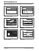
3.0 PIN DESCRIPTIONS
Descriptions of the pins are listed in Table 3-1.
TABLE 3-1: PIN FUNCTION TABLE
3.1 Analog Inputs
The comparator non-inverting and inverting inputs are
high-impedance CMOS inputs with low bias currents.
3.2 Digital Outputs
The comparator outputs are CMOS, open-drain digital
outputs. They are designed to make level shifting and
wired-OR easy to implement.
3.3 Power Supply (V
SS
and V
DD
)
The positive power supply pin (V
DD
) is 1.8V to 5.5V
higher than the negative power supply pin (V
SS
). For
normal operation, the other pins are at voltages
between V
SS
and V
DD
.
Typically, these parts are used in a single (positive)
supply configuration. In this case, V
SS
is connected to
ground and V
DD
is connected to the supply. V
DD
will
need a local bypass capacitor (typically 0.01 µF to
0.1µF) within 2mm of the V
DD
pin. These can share a
bulk capacitor with nearby analog parts (within
100 mm), but it is not required.
MCP6566 MCP6566R MCP6566U MCP6567 MCP6569
Symbol Description
SC70-5,
SOT-23-5
SOT-23-5 SOT-23-5
MSOP,
SOIC
SOIC,
TSSOP
1 1 5 1 1 OUT, OUTA Digital Output (comparator A)
44 3 22V
IN
–, V
INA
– Inverting Input (comparator A)
33 1 33V
IN
+, V
INA
+ Non-inverting Input (comparator A)
52 4 84V
DD
Positive Power Supply
—— — 5 5V
INB
+ Non-inverting Input (comparator B)
—— — 6 6V
INB
– Inverting Input (comparator B)
— — — 7 7 OUTB Digital Output (comparator B)
— — — — 8 OUTC Digital Output (comparator C)
—— — —9V
INC
– Inverting Input (comparator C)
—— — —10V
INC
+ Non-inverting Input (comparator C)
25 2 411V
SS
Negative Power Supply
—— — —12V
IND
+ Non-inverting Input (comparator D)
—— — —13V
IND
– Inverting Input (comparator D)
— — — — 14 OUTD Digital Output (comparator D)