
User manual


MCP651 Input Offset Evaluation Board User’s Guide
DS51834A-page 16 © 2009 Microchip Technology Inc.
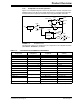
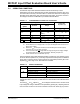
2.5.2 Application
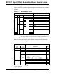
Table 2-3 shows one possible measurement matrix that will allow the user to estimate
key parameters for the DUT. Obviously, other values of V
DD
and V
CAL
could be
selected.
TABLE 2-3: MEASUREMENT MATRIX
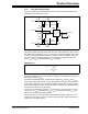
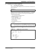
Based on these measurements, we can make the following estimates, where the
V
OST_k
values are calculated from the measured V
Mk
values (see Equation 2-1):
TABLE 2-4: ESTIMATES
Obviously, other values of T
A
, V
DD
, … can be used instead, with the proper adjustments
to these equations.
Operating Inputs Measurement (Note 1)
T
A
(°C)
V
DD
(V)
V
OUT
(V)
V
CM
(V)
G
M
(V/V)
Symbol Comments
+25 5.5 2.75 1.83 40 V
M1
V
OS
and PSRR
-0.30 4 V
M2
CMRR
4.20 V
M3
CMRR
0.20 1.83 V
M4
A
OL
5.30 V
M5
A
OL
2.5 1.25 0.83 V
M6
V
OS
and PSRR
-0.30 V
M7
CMRR
1.20 V
M8
CMRR
0.20 0.83 V
M9
A
OL
2.30 V
M10
A
OL
-40 5.5 2.75 1.83 V
M11
V
OS
at temperature and ΔV
OS
/ΔT
A
+85 V
M12
+125 V
M13
Note 1: Before making these measurements, set up the DUT to the bias point described for
V
M1
. Short V
CALX
to GND. Then start a calibration (CAL) event using S1. Measure
V
M1
, then alter the operating conditions for each succeeding measurement; do not
initiate another calibration event until all measurements are done.
Operating Inputs Estimates
V
DD
(V)
T
A
(°C)
Equations Units
1.8 and 5.5 +25 1/PSRR = (V
OST_1
–V
OST_6
)/(3.0V) µV/V
5.5 -40 V
OS
=V
OST_11
µV
+25 V
OS
=V
OST_1
µV
+85 V
OS
=V
OST_12
µV
+125 V
OS
=V
OST_13
µV
-40 to +125 ΔV
OS
/ΔT
A
=(V
OST_13
–V
OST_11
) / (165°C) µV/°C
+25 1/CMRR = (V
OST_3
–V
OST_2
)/(4.5V) µV/V
1/A
OL
=(V
OST_5
–V
OST_4
)/(5.1V) µV/V
1.8 +25 V
OS
=V
OST_6
µV
1/CMRR = (V
OST_8
–V
OST_7
)/(1.5V) µV/V
1/A
OL
=(V
OST_10
–V
OST_9
) / (2.1V) µV/V