
User manual


MCP651 INPUT OFFSET
EVALUATION BOARD
USER’S GUIDE
© 2009 Microchip Technology Inc. DS51834A-page 11
Chapter 2. Installation and Operation
2.1 INTRODUCTION
This chapter shows how to set up and operate the MCP651 Input Offset Evaluation
Board. Items discussed in this chapter include:
• Required Tools
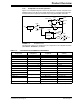
• Configuring the Lab Equipment and PCB
• Operating Conditions
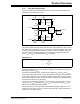
• Calculating DUT Parameters
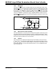
• Settling Time, Noise, and Sampling Rate
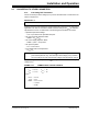
2.2 REQUIRED TOOLS
• (1 or 2) Lab Power Supplies with (two) tracking outputs
- One for +2.5V, GND -2.5V
- The other for V
DDX
, GND, V
SSX
(adjustable up to ±7.0V; optional if
V
DDX
= 2.5V and V
SSX
=-2.5V)
• (0 to 3) independent Lab Power Supplies
- Drive V
CALX
, V
LX
and V
COX
(any or all of these can be not used, as described
in the next section)
- Adjustable up to ±7.0V
• (1 or 2) Voltmeters
- Measure V
M
, V
OUTX
(the latter is for troubleshooting only)
- 1 mV resolution
- -6V to +6V minimum range
- Differential measurement (e.g., hand held meter)