
User manual
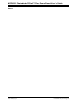
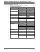
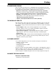

Table Of Contents
MCP6031 Photodiode PICtail™ Plus Demo Board User’s Guide
DS51763A-page 6 © 2008 Microchip Technology Inc.
1.3 MCP6031 PHOTODIODE PICtail™ PLUS DEMO BOARD DESCRIPTION
The MCP6031 Photodiode PICtail™ Plus Demo Board demonstrates how to use a
transimpedance amplifier, which consists of MCP6031 high precision op amp and
external resistors, to convert photo-current (I
S
) to voltage. The circuit was not calibrated
for absolute accuracy.
The RC low-pass filter that is implemented in this circuit can remove the high frequency
noise and interference from the signal path prior to the analog-to-digital (A/D)
conversion.
The PICmicro
®
on the Explorer 16 Development Board communicates with the
MCP6031 Photodiode PICtail™ Plus Demo Board and completes the analog-to-digital
conversion.
The measured voltage (V
OUT
) and calculated illuminance (L) will be shown on LCD
screen on board. The illuminance (L) will be calculated by the equation:
EQUATION 1-1:
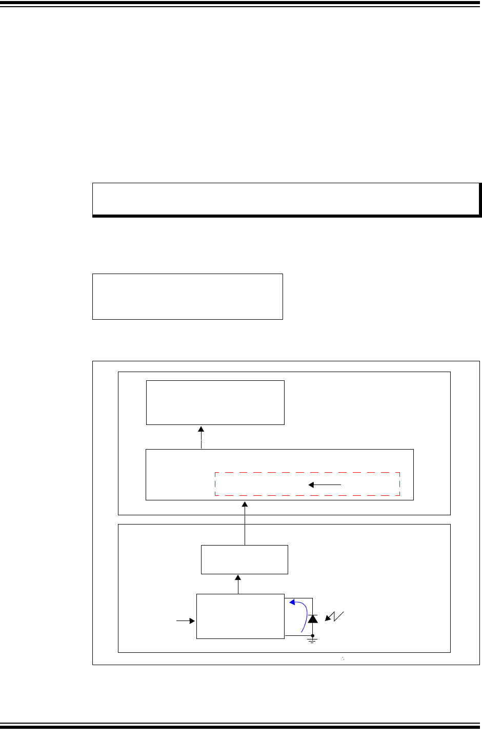
Figure 1-2 shows the block diagram of the MCP6031 Photodiode PICtail™ Plus Demo
Board .
FIGURE 1-2: MCP6031 Photodiode PICtail™ Plus Demo Board Function
Block Diagram.
Note: For high measurement accuracy, an external stand-alone ADC with higher
resolution needs to be used.
V
OUT
R
1
⁄
()10000 l
X
/70
μ
A()
L = illuminance (l
x
)
=
MCP6031
Explorer 16 Development Board
PN334 Photodiode
+
-
RC Low-Pass
Filter
10 Bit ADC Module V
REF
= 3.3V
LCD Screen
V
DD
= V
REF
MCP603x Photodiode
PICtail™ Plus Demo Board
Transimpedance
Amplifier
PIC24FJ128 Microcontroller
Vout = ___________ V
L = ____________ lx
V
OUT
I
S
= 3.3V