
Datasheet


MCP4XXX Digital Potentiometer Daughter Board User’s Guide
DS51621A-page 14 © 2006 Microchip Technology Inc.
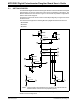
FIGURE 2-6: Jumper JP1, JP2, JP3, JP4, JP5, and JP6 Configurations.
JP3, JP5, JP6
JP1, JP2, JP4
JP6 - U2-P1W is floating
(or pulled to VDD via R16)
JP5 - U2-P1B not connected to U2-P1W
JP3 - U2-P1A is floating
(or pulled to VDD via R2)
JP6 - U2-P1W is connected to VDD
JP5 - U2-P1B not connected to U2-P1W
JP3 - U2-P1A is connected to VDD
JP4 - U2-P0A is floating
(or pulled to VDD via R3)
JP2 - U2-P0B is floating
(or pulled to VSS via R1)
JP1 - U2-P0W not connected to U2-P0B
JP4 - U2-P0A is connected to VDD
JP2 - U2-P0B is connected to VSS
JP1 - U2-P0W is connected to U2-P0B