
Datasheet


Installation and Operation
© 2006 Microchip Technology Inc. DS51621A-page 13
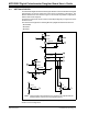
FIGURE 2-5: Jumper JP7, JP9, JP10, JP11, JP12, and JP13 Configurations.
JP11, JP12, & JP13
JP7
JP9:JP10 - U1 Pot0 to U2 Pots
U3 Pot NOT
connected
U3 Pot connected
to U1 Pot0
U1 Pot0 NOT connected
to U2 Pots
U1 Pot0 connected to
U2 Pots:
JMP4 SDO selection is
connected to U2-SI pin and
U1-P0W → U2-P0W
P1-P0A → U2-P1B
U1 Serial Out (SO)
connected to U2
to U1 Pot0
U3-A → U1-P0A
U3-W → U1-P0W
U3-B → U1-P0B
Serial In (SI)
(U2 “daisy chained” to U1)
U1-SO signal goes to U5-1
(input to 2-input OR gate)
(typically device in U1
is removed for this
configuration)