
Datasheet


Installation and Operation
© 2006 Microchip Technology Inc. DS51621A-page 11
2.3.1.1 JUMPERS
Figure 2-3 through Figure 2-6 show the function of the demo board jumpers. Some of
the jumpers configure the interface connections, while other configure the resistor
network configuration.
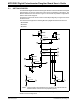
FIGURE 2-3: Jumper JMP2, JMP3, and JMP4 Configurations.
JMP3 - SPI Clock Source
JMP2 - SPI Data Out Destination
JMP4 - SPI Data In Source
Using PICDEM
HPC Board (RC3)
Using PICDEM
FS USB Board (RB1)
Using PICDEM
HPC Board (RC4)
Using PICDEM
FS USB Board (RB0)
Using PICDEM
HPC Board (RC5)
Using PICDEM
FS USB Board (RC7)