
Datasheet


MCP4XXX Digital Potentiometer Daughter Board User’s Guide
DS51621A-page 8 © 2006 Microchip Technology Inc.
2.3 GETTING STARTED
The MCP4XXX Digital Potentiometer Daughter Board is a board that allows the Digital
Potentiometer circuit to be configured in many forms for evaluation of the device. The
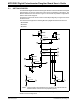
Resistor Network Circuit is shown in Figure 2-1 and shows the possible configurations
that the demo board supports.
The passive components use the surface-mount 805 package layout. Figure 2-2 shows
the board circuit.
This demo board supports the following Microchip Digital Potentiometers devices:
• MCP42XXX
• MCP4021
•MCP4011
FIGURE 2-1: MCP4XXX Digital Potentiometer Daughter Board Resistor
Network Circuit Configuration.
U1-P0A
U1-P0W
U1-P0B
NOTE
U1-P1A
U1-P1W
U1-P1B
U2-P0A
U2-P0W
U2-P0B
U2-P1A
U2-P1W
U2-P1B
NOTE
NOTE
NOTE
U3-A
U3-W
U3-B
Note: These footprints are provided so the customer can populate with the
desired resistor value or leave unpopulated (open).