
Datasheet


MCP4XXX DIGITAL POTENTIOMETER
DAUGHTER BOARD USER’S GUIDE
© 2006 Microchip Technology Inc. DS51621A-page 7
Chapter 2. Installation and Operation
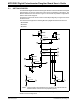
2.1 INTRODUCTION
This daughter board allows evaluation of digital potentiometer devices in different
circuit configurations. The board supports the MCP42XXX devices and the
MCP4011/MCP4021 devices.
This board is intended to be “plugged into” the 28-pin header of the PICDEM™ Demo
Boards. The board may also be “jumpered” into a desired application circuit.
2.2 FEATURES
The MCP4XXX Digital Potentiometer Daughter Board has the following features:
• Header to interface to PICDEM™ boards using 28-pin header, including:
- PICDEM™ HPC Explorer Demo Board
- PICDEM™ FS USB Demo Board
- PICDEM™ 2 Plus Demo Board (Rev 5 or later)
-PICDEM™ LCD
• TC1240A Voltage Doubler to generate V
IHH
voltage for WiperLock™ Technology
evaluation
• Jumpers for configuration of U1-Pot0, U2-Pot0, and U2-Pot1 terminal connections
• Jumpers for MCP4021 Pot (A, W, and B) to replace U1-Pot0 in desired circuit
• Jumpers for routing signals (SI, SO, SCK, and CS
) from either a PICDEM HPC
Demo board or a PICDEM FS USB Demo Board
• Pads for easy connection to the Digital Potentiometer signals, including the
Resistor Network Terminals and the Serial Interface signals
• Connection terminals may be either through-hole or surface-mount