
User manual


Quick Start Instructions
© 2009 Microchip Technology Inc. DS51837A-page 27
1.3.2.12 EXAMPLE 6: SEQUENTIAL WRITE FOR DAC INPUT REGISTERS AND
EEPROM
This command writes to the DAC input registers and EEPROM sequentially from a start
channel to the channel D. The input register is written at the ACK pulse of the input data
byte of each register. However, the EEPROM are written altogether at the same time
sequentially at the end of the last byte. The EEPROM writing activity can be monitored
through the RDY/BSY
bit and pin. See the MCP4728 data sheet for details.
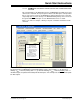
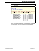
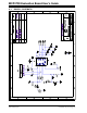
Figure 1-18 shows an example of writing a script file on PICkit Serial PC GUI for this
command.
.
FIGURE 1-18: Writing Script file to write the Channel B to Channel D. This command writes to both
the input registers and EEPROM: (a) Channel B Settings: V
REF
= V
DD
and Gain = 1. (b) Channel C
Settings: V
REF
= Internal (2.048V), Gain = 1. (c) Channel D Settings: V
REF
= Internal (2.048V), Gain = 2.
The DAC outputs are updated immediately with the ACK pulse. This example uses the U
DAC bit to update
the DAC outputs.
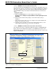
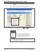
1. To change value:
• Click this box and
type a new value
2. To delete or Insert box:
• Select the box and
right click the mouse
button for options
available
3. Make sure the listed
parameters in “script
Detail” are in the exact
order as shown here.