
User manual

MCP4728 Evaluation Board User’s Guide
DS51837A-page 24 © 2009 Microchip Technology Inc.
1.3.2.10 EXAMPLE 5: SINGLE WRITE COMMAND FOR DAC INPUT REGISTER
AND EEPROM
This command writes to a single DAC input register and its EEPROM. Both input
register and EEPROM are written at the acknowledge pulse of the input data byte. The
EEPROM program activity can be monitored through the RDY/BSY
bit and pin. See the
MCP4728 data sheet for details.
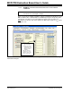
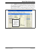
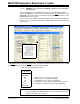
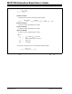
Figure 1-16 shows an example of writing a script file. In this example, the PICkit Serial
Analyzer sends a single write command to the MCP4728 for the DAC A (Channel A)
input register.
.
FIGURE 1-16: Writing Script File to Write the Channel A Register and its EEPROM with FFFh Using
a Single Write Command. The Channel A output is updated immediately with the ACK Pulse. This example
uses UDAC
Bit, instead of using LDAC pin, to update the DAC output.
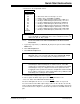
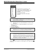
• Parameters in the Script Detail column:
1. To change value:
• Click this box and
type a new value
2. To delete or Insert box:
• Select the box and
right click the mouse
button for options
available
3. Make sure the listed
parameters in “script
Detail” are in the exact
order as shown here.
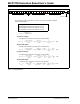
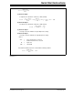
Script Detail
I2CSTART *
I2CWRTBYT *
04 -------> This means there are four bytes to send.
C0 -------> Address byte = 1100-0000 (See Note).
58 -------> Command Type and selection of Channel A.
0F -------> Configuration register bits and data nibble for Channel A.
FF -------> Data byte for Channel A (register and its EEPROM).
I2CSTOP *
Note: All parameters above must be listed in order. The parameter above with *
are not modifiable. The MCP4728 device on the evaluation board has I
2
C
address bits (A2, A1, A0) = (0,0,0).