
User manual

MCP4728 Evaluation Board User’s Guide
DS51837A-page 20 © 2009 Microchip Technology Inc.
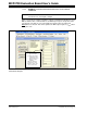
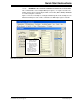
FIGURE 1-13: V
OUT
for Example 3: Fast Write Command for Various V
OUT
. V
REF
= V
DD
and
Gain = 1 for All Channels.
V
OUT
V
REF
D
n
×
()
4096
------------------------------ -
G
x
=
V
OUT
A
V
DD
4095
×
()
4096
--------------------------------- -
V
DD
4096 1–
4096
-------------------- -
⎝⎠
⎛⎞
V
DD
1
1
4096
----------- -
–
⎝⎠
⎛⎞
V
DD
LSB–====
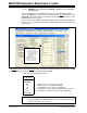
Next DAC Channels
Fast Mode Write Command
In Script file, Dn for Channel A = 0FFF (hex) = 4095 (decimal)
(A) Channel A Output:
(B) Channel B Output:
In Script file, Dn for Channel B = 07FF (hex) = 2047 (decimal)
V
OUT
B
V
DD
2047
×
()
4096
--------------------------------- -
V
DD
2048 1–
4096
-------------------- -
⎝⎠
⎛⎞
V
DD
2
---------- -
1
2
4096
----------- -
–
⎝⎠
⎛⎞
V
DD
2
---------- -LSB–====
(C) Channel C Output:
In Script file, Dn for Channel C = 03FF (hex) = 1023 (decimal)
V
OUT
C
V
DD
1023
×
4096
--------------------------------
V
DD
1024 1–
4096
-------------------- -
⎝⎠
⎛⎞
V
DD
4
---------- -
1
4
4096
----------- -
–
⎝⎠
⎛⎞
V
DD
4
---------- -LSB–====
(D) Channel D Output:
In Script file, Dn for Channel D = 01FF (hex) = 511 (decimal)
V
OUT
D
V
DD
511
×
4096
-----------------------------
V
DD
512 1–
4096
----------------- -
⎝⎠
⎛⎞
V
DD
8
---------- -
1
8
4096
----------- -–
⎝⎠
⎛⎞
V
DD
8
---------- -LSB–====
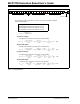
DAC Input Data of Channel A = 001111-11111111
DAC A
DAC Input Data of Channel B = 000111-11111111
DAC Input Data of Channel C = 000011-11111111
DAC Input Data of Channel D = 000001-11111111
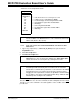
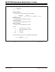
The following example shows when the device receives the Fast Write command
with the following data:
Start
Stop
1 1 0 0 0 0 0 0 A 0 0 0 0 D11 D10 D9 D8 A D7 D6 D5 D4 D3 D2 D1 D0 A
Address Byte
2nd Byte
3rd Byte1st Byte