
User manual

Quick Start Instructions
© 2009 Microchip Technology Inc. DS51837A-page 19
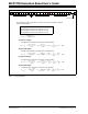
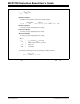
• Parameters in the Script Detail column:
1.3.2.7 SAVE THE SCRIPT FILE AND PROGRAMMING THE MCP4728 DAC
REGISTERS
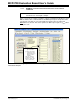
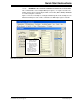
1. Type in any script name (i.e., MCP4728_W_Fast) in the space below the Script
Name menu.
2. Click Save Script button.
3. Click Execute Script button.
4. You can also see the SCL and SDA waveforms using the Oscilloscope.
5. Read the V
OUT
voltage at the V
OUT
test pads:
In order to update the DAC output register, the LDAC pin must be “Low”.
• Press “S1” button in the MCP4728 Evaluation Board.
The device will update the V
OUT
as soon as the LDAC pin switch S1 is pressed.
You can now measure the DAC output voltages (V
OUT
A, V
OUT
B, V
OUT
C, V
OUT
D)
using a voltmeter. When Examples 1, 2, and 3 are executed sequentially, all channels
use an internal reference. Figure 1-13 shows the expectation of each DAC channel out-
puts.
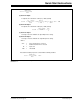
Script Detail
I2CSTART *
I2CWRTBYT *
09 -------> This means there are nine bytes to send.
C0 -------> Address byte = 1100-0000 (See Note).
0F -------> 1st byte of DAC A Register (Channel A) = 0000-1111
FF -------> 2nd byte of DAC A Register (Channel A) = 1111-1111
07 -------> 1st byte of DAC B Register (Channel B) = 0000-0111
FF -------> 2nd byte of DAC B Register (Channel B) =1111-1111
03 -------> 1st byte of DAC C Register (Channel C) = 0000-0011
FF -------> 2nd byte of DAC C Register (Channel C) = 1111-1111
01 -------> 1st byte of DAC D Register (Channel D) = 0000 -0001
FF -------> 2nd byte of DAC D Register (Channel D) = 1111-1111
I2CSTOP *
Note: All parameters above must be listed in order. The parameter above with *
are not modifiable. The MCP4728 device on the evaluation board has I
2
C
address bits (A2, A1, A0) = (0,0,0).
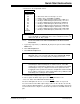
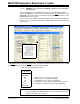
Note: At this point, the PICkit Serial transmits the I
2
C Write Command to the
MCP4728 device. The saved file name will appear in Users I2C Scripts
column, and can be re-used any time by selecting the file name.
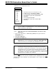
Note: When you click on the “Execute Script” menu, the “Busy” LED on the PICkit
Serial Analyzer will momentarily turn on and then turn off. If the LED
remains ON, a communications problem has occurred. Remove the PICkit
Serial Analyzer from your computer and recheck the parameter values
including the order of parameters under the “Script Detail” column including
the I
2
C address of the device, and try again until the “Busy” LED turns OFF
immediately after sending the I
2
C command.