
User manual

Quick Start Instructions
© 2009 Microchip Technology Inc. DS51837A-page 15
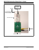
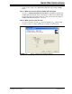
• Modify the parameters in the Script Detail column as below:
1.3.2.3 SAVE THE SCRIPT FILE AND PROGRAMMING THE MCP4728 DAC
REGISTERS
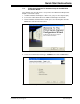
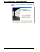
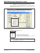
1. Type in a script file name (i.e., MCP4728_W_VrfSel) in the space below the
Script Name menu.
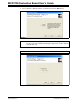
2. Click Save Script button.
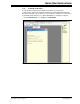
3. Click Execute Script button.
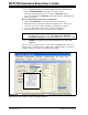
4. You can also see the SCL and SDA waveforms using an Oscilloscope.
Script Detail
I2CSTART *
I2CWRTBYT *
02 --------> This means there are two bytes to send.
C0 --------> Address byte = 1100-0000 (See Note).
80 --------> 1’st byte (000-0000) selecting external V
REF
.
I2CSTOP *
Note: All 6 parameters above must be listed in order. The parameters with * are
not modifiable. The MCP4728 device on the evaluation board has I
2
C
address bits (A2, A1, A0) = (0,0,0).
Note: At this point, the PICkit Serial Analyzer transmits the I
2
C Write Command
to the MCP4728 device. The saved file name will appear in the Users I2C
Scripts column, and can be re-used any time by selecting the file name.
Note: When you click on the “Execute Script” menu, the “Busy” LED on the PICkit
Serial Analyzer will momentarily turn on and then turn off. If the LED
remains ON, a communications problem has occurred. Remove the PICkit
Serial Analyzer from your computer and recheck the parameter values,
including the order of parameters under the “Script Detail” column including
the I
2
C address of the device, and try again until the “Busy” LED turns OFF
immediately after sending the I
2
C command.