
User manual

Quick Start Instructions
© 2009 Microchip Technology Inc. DS51837A-page 7
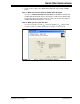
1.3 GETTING STARTED WITH PICKIT SERIAL ANALYZER
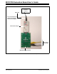
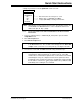
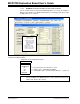
Figure 1-1 shows the MCP4728 Evaluation Board, and Figure 1-2 shows the
connection of the MCP4728 Evaluation Board and PICkit Serial Analyzer.
The following steps describe how to use them together:
1. Connect the MCP4728 Evaluation Board’s 6-pin socket to the PICkit Serial
Analyzer as shown in Figure 1-2.
2. Connect the oscilloscope probes to the SCL and SDA test terminals (optional).
3. Connect a multimeter to one of the DAC’s output test terminal.
4. V
DD
Selection: You can use the V
DD
from the PICkit Serial Analyzer or use your
own external V
DD
. The JP1 connector selects the V
DD
path.
(a) Connect JP1, if using V
DD
from PICkit Serial Analyzer,
(b) Disconnect JP1 and apply V
DD
at V
DD
1 pin, if you are using an external V
DD
.
• I
2
C device code of MCP4728: ‘1100’
• A2, A1, A0 Address Bits: Pre-programmed to‘000’.
5. Connecting V
DD
: LED D1 turns on when V
DD
is applied. The PICkit Serial
Analyzer will provide V
DD
automatically, if it is connected to the PC. Make sure
LED D1 turns on.
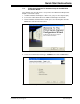
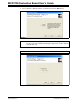
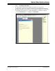
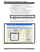
6. Use the PICkit Serial Analyzer PC GUI to send I
2
C write and read commands.