MCP4728 Evaluation Board User’s Guide © 2009 Microchip Technology Inc.
Note the following details of the code protection feature on Microchip devices: • Microchip products meet the specification contained in their particular Microchip Data Sheet. • Microchip believes that its family of products is one of the most secure families of its kind on the market today, when used in the intended manner and under normal conditions. • There are dishonest and possibly illegal methods used to breach the code protection feature.
MCP4728 EVALUATION BOARD USER’S GUIDE Table of Contents Preface ........................................................................................................................... 1 Introduction............................................................................................................ 1 Document Layout .................................................................................................. 1 Conventions Used in this Guide ...................................................
MCP4728 Evaluation Board User’s Guide NOTES: DS51837A-page iv © 2009 Microchip Technology Inc.
MCP4728 EVALUATION BOARD USER’S GUIDE Preface NOTICE TO CUSTOMERS All documentation becomes dated, and this manual is no exception. Microchip tools and documentation are constantly evolving to meet customer needs, so some actual dialogs and/or tool descriptions may differ from those in this document. Please refer to our web site (www.microchip.com) to obtain the latest documentation available. Documents are identified with a “DS” number.
MCP4728 Evaluation Board User’s Guide CONVENTIONS USED IN THIS GUIDE This manual uses the following documentation conventions: DOCUMENTATION CONVENTIONS Description Represents Examples Code (Courier font): Plain characters Sample code Filenames and paths #define START c:\autoexec.bat Angle brackets: < > Variables
Preface THE MICROCHIP WEB SITE Microchip provides online support via our web site at www.microchip.com. This web site is used as a means to make files and information easily available to customers.
MCP4728 Evaluation Board User’s Guide NOTES: DS51837A-page 4 © 2009 Microchip Technology Inc.
MCP4728 EVALUATION BOARD USER’S GUIDE Chapter 1. Quick Start Instructions 1.1 INTRODUCTION The following sections provide an overview of the MCP4728 Evaluation Board and instructions on how to program the DAC register and the EEPROM of the MCP4728 using the PICkitTM Serial Analyzer. The following sections cover the topics: • Description of the MCP4728 Evaluation Board • How to use the MCP4728 Evaluation Board with the PICkit Serial Analyzer 1.
MCP4728 Evaluation Board User’s Guide FIGURE 1-1: TABLE 1-1: Test Terminals Front View of the MCP4728 Evaluation Board. TEST TERMINALS ON THE MCP4728 EVALUATION BOARD Description VOUT A VOUT B VOUT C VOUT D SCL DAC channel A output DAC channel B output DAC channel C output DAC channel D output This terminal is connected to the I2C SCL pin of the MCP4728. (See Note 1). SDA This terminal is connected to the I2C SDA pin of the MCP4728. (See Note 1).
Quick Start Instructions 1.3 GETTING STARTED WITH PICKIT SERIAL ANALYZER Figure 1-1 shows the MCP4728 Evaluation Board, and Figure 1-2 shows the connection of the MCP4728 Evaluation Board and PICkit Serial Analyzer. The following steps describe how to use them together: 1. Connect the MCP4728 Evaluation Board’s 6-pin socket to the PICkit Serial Analyzer as shown in Figure 1-2. 2. Connect the oscilloscope probes to the SCL and SDA test terminals (optional). 3.
MCP4728 Evaluation Board User’s Guide . Personal Computer USB Cable Connected between the PICkit Serial Analyzer and Personal Computer PICkit Serial Analyzer DAC Output (Channel B) MCP4728 Evaluation Board FIGURE 1-2: DS51837A-page 8 MCP4728 Evaluation Board with the PICkit Serial Analyzer. © 2009 Microchip Technology Inc.
Quick Start Instructions 1.3.1 PICkit Serial Analyzer PC Software Setup for the MCP4728 Evaluation Board The following steps describe how to set up and use the PICkit Serial Analyzer PC Graphic User Interface (GUI). 1. Install the PICkit Serial Analyzer software onto your personal computer (PC). 2. Connect the USB cable between the PICkit Serial Analyzer and the PC. 3. Run the PICkit Serial PC Software: It will open to the following GUI. Click the Next button and follow the instructions.
MCP4728 Evaluation Board User’s Guide 5. Select 100 kHz or 400 kHz. Either one will be fine. Click the Next button. FIGURE 1-5: Note: Step 2 - I2C Communication Speed Selection. The MCP4728 device supports the I2C bus data rate up to 3.4 MHz, but the current version of the PICkit Serial Analyzer supports the I2C bus data rate up to 400 kHz only. 6. Select No on Enable Pull-ups and click the Next button. Note: The MCP4728 Evaluation Board has its own pull-up resistors.
Quick Start Instructions 7. Select the VDD voltage of the MCP4728 Evaluation Board and click the Next button. Case 1: When you use VDD from the PICkit Serial Analyzer: If you choose PICkit Serial will power your device and 5 Volts as shown below, the MCP4728 Evaluation Board is powered by the 5V DC from the PICkit Serial Analyzer through the JP1 jumper. In this case, make sure that the JP1 jumper on the MCP4728 Evaluation Board is connected.
MCP4728 Evaluation Board User’s Guide 8. Click the OK button. You have made all of the PICkit Serial Analyzer Configuration Setups. You are now ready to read/write MCP4728 registers and EEPROM. FIGURE 1-8: DS51837A-page 12 Configuration Wizard - Finishing Step. © 2009 Microchip Technology Inc.
Quick Start Instructions 1.3.2 Creating Script Files: A script file that is running on the PICkit Serial PC GUI is needed for the communications between the PICkit Serial Analyzer and the MCP4728 Evaluation Board. The following steps show how to create script files and how to use them. Refer to the PICkit Serial Analyzer User’s Guide (DS51647) for creating the Script file. • Select Communication -----> Script ---> Script Builder FIGURE 1-9: © 2009 Microchip Technology Inc.
MCP4728 Evaluation Board User’s Guide 1.3.2.1 CREATING SCRIPT FILE FOR CONFIGURATION BYTE WRITING 1. Click on WriteBlockAddrA8 in “Example I2C Scripts” column. This will result in filling in the spaces under the Script Detail column. You can now modify the Script Detail column parameters by clicking with the right mouse button. How to modify the parameters box in Script Details: 1. Under the Script Detail box, select the item in the parameter box. 2. Right click the mouse button.
Quick Start Instructions • Modify the parameters in the Script Detail column as below: Script Detail I2CSTART * I2CWRTBYT * 02 --------> This means there are two bytes to send. C0 --------> Address byte = 1100-0000 (See Note). 80 --------> 1’st byte (000-0000) selecting external VREF. I2CSTOP * Note: 1.3.2.3 All 6 parameters above must be listed in order. The parameters with * are not modifiable. The MCP4728 device on the evaluation board has I2C address bits (A2, A1, A0) = (0,0,0).
MCP4728 Evaluation Board User’s Guide 1.3.2.4 EXAMPLE 2: SELECTING GAIN OF EACH DAC CHANNEL You can select the Gain of each channel individually. Figure 1-11 shows an example of writing a new script file on the PICkit Serial PC GUI for selecting the gain option. In this example, Gain of 1 is selected. . 1. 2. 3.
Quick Start Instructions 1.3.2.5 SAVE THE SCRIPT FILE AND PROGRAMMING THE MCP4728 DAC REGISTERS 1. Type in any script name (i.e., MCP4728_W_GainSl) in the space below the Script Name menu. 2. Click Save Script button. 3. Click Execute Script button. Note: At this point, the PICkit Serial transmits the I2C Write Command to the MCP4728 device. The saved file name will appear in Users I2C Scripts column, and can be re-used any time by selecting the file name. 4.
MCP4728 Evaluation Board User’s Guide 1.3.2.6 Note: EXAMPLE 3: WRITING DAC REGISTERS WITH A FAST WRITE COMMAND Please refer to the MCP4728 data sheet for the Fast Write Command structure before excising this example. Figure 1-12 shows an example of writing a script file on PICkit Serial PC GUI for a Fast Write Command. This command writes to the DAC input registers and power-down selection bits. The data are sent sequentially from channel A to the channel D. EEPROM is not affected.
Quick Start Instructions • Parameters in the Script Detail column: Script Detail I2CSTART I2CWRTBYT 09 C0 0F FF 07 FF 03 FF 01 FF I2CSTOP Note: 1.3.2.7 * * -------> This means there are nine bytes to send. -------> Address byte = 1100-0000 (See Note).
MCP4728 Evaluation Board User’s Guide Start 1st Byte 1 1 0 0 0 0 0 Address Byte 0 A 0 0 0 0 D11 Fast Mode Write Command Stop 3rd Byte 2nd Byte D10 D9 D8 A D7 D6 D5 D4 D3 D2 D1 D0 A DAC A Next DAC Channels The following example shows when the device receives the Fast Write command with the following data: DAC Input Data of Channel A = 001111-11111111 DAC Input Data of Channel B = 000111-11111111 DAC Input Data of Channel C = 000011-11111111 DAC Input Data of Channel D = 0000
Quick Start Instructions 1.3.2.8 EXAMPLE 4: MULTI-WRITE COMMAND FOR DAC INPUT REGISTERS This command writes to the multiple DAC input registers, one register at a time. The writing channel register is defined by the DAC selection bits (DAC1, DAC0). EEPROM is not affected by this command. Figure 1-14 shows an example of creating the PICkit Script file. In this example, the the PICkit Serial Analyzer sends a write command to the DAC input registers A and B. 1. 2. 3.
MCP4728 Evaluation Board User’s Guide • Parameters in the Script Detail column: Script Detail I2CSTART I2CWRTBYT 07 C0 40 0F FF 02 08 00 I2CSTOP Note: 1.3.2.9 * * -------> This means there are seven bytes to send. -------> Address byte = 1100-0000 (See Note).
Quick Start Instructions ( V REF × D n ) V OUT = ------------------------------- G x 4096 (A) Channel A Output: In Script file, Dn for Channel A = 0FFF (hex) = 4095 (decimal) V OUT A ( V DD × 4095 ) 4096 – 1 1 -⎞ = V – LSB = ---------------------------------- = V DD ⎛⎝ ---------------------⎞⎠ = V DD ⎛⎝ 1 – ----------DD 4096 4096 4096⎠ (B) Channel B Output: In Script file, Dn for Channel B = 0800 (hex) = 2048 (decimal) V OUT B ( V DD × 2048 ) V DD = ---------------------------------- = ---------4096 2 (C
MCP4728 Evaluation Board User’s Guide 1.3.2.10 EXAMPLE 5: SINGLE WRITE COMMAND FOR DAC INPUT REGISTER AND EEPROM This command writes to a single DAC input register and its EEPROM. Both input register and EEPROM are written at the acknowledge pulse of the input data byte. The EEPROM program activity can be monitored through the RDY/BSY bit and pin. See the MCP4728 data sheet for details. Figure 1-16 shows an example of writing a script file.
Quick Start Instructions 1.3.2.11 SAVE THE SCRIPT FILE AND PROGRAMMING THE MCP4728 DAC REGISTERS 1. Type in any script name (i.e., MCP4728_W_SingEE) in the space below the Script Name menu. 2. Click Save Script button. 3. Click Execute Script button. Note: At this point, the PICkit Serial transmits the I2C Write Command to the MCP4728 device. The saved file name will appear in Users I2C Scripts column, and can be re-used any time by selecting the file name. 4.
MCP4728 Evaluation Board User’s Guide ( V REF × D n ) V OUT = ------------------------------- G x 4096 (A) Channel A Output: In Script file, Dn for Channel A = 0FFF (hex) = 4095 (decimal) V OUT A ( V DD × 4095 ) 4096 – 1 1 -⎞ = = ---------------------------------- = V DD ⎛ ---------------------⎞ = V DD ⎛ 1 – ----------V DD – LSB ⎝ 4096 ⎠ ⎝ 4096 4096⎠ (B) Channel B Output: No change. Keep its output with previous settings. (C) Channel C Output: No change. Keep its output with previous settings.
Quick Start Instructions 1.3.2.12 EXAMPLE 6: SEQUENTIAL WRITE FOR DAC INPUT REGISTERS AND EEPROM This command writes to the DAC input registers and EEPROM sequentially from a start channel to the channel D. The input register is written at the ACK pulse of the input data byte of each register. However, the EEPROM are written altogether at the same time sequentially at the end of the last byte. The EEPROM writing activity can be monitored through the RDY/BSY bit and pin.
MCP4728 Evaluation Board User’s Guide • Parameters in the Script Detail column: Script Detail I2CSTART I2CWRTBYT 08 C0 52 0F FF 8F FF 90 FF I2CSTOP Note: 1.3.2.13 * * -------> This means there are eight bytes to send. -------> Address byte = 1100-0000 (See Note). -------> Command Type and Ch. B is a starting channel -------> Configuration register bits and data nibble for Ch. B -------> Data byte for Ch. B -------> Configuration register bits and data nibble for Ch. C -------> Data byte for Ch.
Quick Start Instructions ( V REF × D n ) V OUT = ------------------------------- G x 4096 (A) DAC A Output: No change. Keep its output with previous settings.
MCP4728 Evaluation Board User’s Guide 1.3.2.14 EXAMPLE 7: TESTING EEPROM FEATURES The device will upload the EEPROM data to both input and output DAC registers (a) during power-up sequence or (b) when it receives the General Call Reset command. One of these conditions makes the analog outputs available immediately with their current EEPROM settings. Note that the Power-Down bit must be cleared for the output. • Testing Procedure: a. Write to the EEPROM with one of the examples shown earlier (i.e.
Quick Start Instructions Note: In Figure 1-20, the script file called “MCP4728_Read” was created, saved and executed. . DAC A Register DAC C Register DAC B Register DAC A EEPROM DAC C EEPROM DAC D Register Ch. A Register: C0-0F-FF: Ch. A EEPROM: C8-0F-FF: Ch. B Register: D0-0F-FF: Ch. B EEPROM: D8-0F-FF: Ch. C Register: E0-8F-FF: Ch. C EEPROM: E8-0F-FF: Ch. D Register: F0-90-FF: Ch.
MCP4728 Evaluation Board User’s Guide 1.3.2.16 EXAMPLE 9: WRITE POWER-DOWN SELECTION BITS IN DAC INPUT REGISTER This command writes power-down bits to the DAC input registers. Figure 1-22 shows an example of writing a new script file for Power-Down mode. . 1. 2. 3. To change value: • Click this box and type a new value To delete or Insert box: • Select the box and right click the mouse button for options available Make sure the listed parameters in “script Detail” are in the exact order as shown here.
Quick Start Instructions 1.3.2.17 SAVE THE SCRIPT FILE AND PROGRAMMING THE MCP4728 DAC REGISTERS 1. Type in any script name (i.e., MCP4728_W_PDown) in the space below the Script Name menu. 2. Click Save Script button. 3. Click Execute Script button. Note: At this point, the PICkit Serial transmits the I2C Write Command to the MCP4728 device. The saved file name will appear in Users I2C Scripts column, and can be re-used any time by selecting the file name. 4.
MCP4728 Evaluation Board User’s Guide NOTES: DS51837A-page 34 © 2009 Microchip Technology Inc.
MCP4728 EVALUATION BOARD USER’S GUIDE Appendix A. Schematic and Layouts A.1 INTRODUCTION This appendix contains the following schematics and layouts for the MCP4728 Evaluation Board: • • • • • Board – Schematic Board – Top Silk, Top Pads, and Top Copper Layer Board – Top Copper and Pads Layer Board – Top Pads and Silk Layer Board – Bottom Copper Layer © 2009 Microchip Technology Inc.
MCP4728 Evaluation Board User’s Guide A.2 BOARD – SCHEMATIC DS51837A-page 36 © 2009 Microchip Technology Inc.
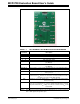
Schematic and Layouts A.3 BOARD – TOP SILK, TOP PADS AND TOP COPPER © 2009 Microchip Technology Inc.
MCP4728 Evaluation Board User’s Guide A.4 BOARD – TOP COPPER AND PADS DS51837A-page 38 © 2009 Microchip Technology Inc.
Schematic and Layouts A.5 BOARD – TOP PADS AND SILK © 2009 Microchip Technology Inc.
MCP4728 Evaluation Board User’s Guide A.6 BOARD – BOTTOM COPPER LAYER DS51837A-page 40 © 2009 Microchip Technology Inc.
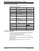
MCP4728 EVALUATION BOARD USER’S GUIDE Appendix B. Bill Of Materials (BOM) TABLE B-1: Qty BILL OF MATERIALS Reference Description Manufacturer Part Number 4 C1, C3, C4, C5 CAP 1000PF 50V CERAMIC X7R 0603 Panasonic® - ECG ECJ-1VB1H102K 1 C2 CAP CERAMIC 10UF 6.3V X5R 0603 Panasonic - ECG ECJ-1VB0J106M 1 D1 LED RED CLEAR 0805 SMD Lite-On Inc LTST-C170CKT CONN HEADER 6POS .100 R/A TIN Molex®/Waldom® Electron- 22-05-2061 ics Corp 1 J1 2 JP1, JP2 CONN HEADER 2POS .
MCP4728 Evaluation Board User’s Guide NOTES: DS51837A-page 42 © 2009 Microchip Technology Inc.
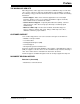
MCP4728 EVALUATION BOARD USER’S GUIDE Appendix C. MCP4728 Read/Write Commands C.1 INTRODUCTION Table summarizes the write command types and their functions. The write command is defined by using three write command type bits (C2, C1, C0) and two write function bits (W1, W0). Writing and reading the I2C address bits are not demonstrated with the PICKit Serial Analyzer. Please see the MCP4728 data sheet for more details on the commands.
MCP4728 Evaluation Board User’s Guide TABLE C-1: WRITE COMMAND TYPES (CONTINUED) Command Field C2 C1 C0 Write Function W1 Command Name Function W0 Write VREF, Gain, and Power-Down Select Bits (Note 4) 1 0 0 Not Used 1 1 0 Not Used 1 0 1 Not Used Note 1: 2: 3: 4: Write Reference This command writes reference (VREF) selection bits of each channel. (VREF) selection bits to Input Registers Write Gain selection bit to Input Registers This command writes Gain selection bits of each channel.
MCP4728 Read/Write Commands NOTES: © 2009 Microchip Technology Inc.
WORLDWIDE SALES AND SERVICE AMERICAS ASIA/PACIFIC ASIA/PACIFIC EUROPE Corporate Office 2355 West Chandler Blvd. Chandler, AZ 85224-6199 Tel: 480-792-7200 Fax: 480-792-7277 Technical Support: http://support.microchip.com Web Address: www.microchip.