
Datasheet


MCP4728
DS22187E-page 36 © 2010 Microchip Technology Inc.
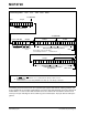
5.6.3 SEQUENTIAL WRITE COMMAND:
WRITE DAC INPUT REGISTERS
AND EEPROM SEQUENTIALLY
FROM STARTING CHANNEL TO
CHANNEL D
(C2=0, C1=1, C0=0; W1=1, W0=0)
When the device receives this command, it writes the
input data to the DAC input registers sequentially from
the starting channel to channel D, and also writes to
EEPROM sequentially. The starting channel is
determined by the DAC1 and DAC0 bits. Table 5-2
shows the functions of the channel selection bits for the
sequential write command.
When the device is writing EEPROM, the RDY/BSY
bit
stays “Low” until the EEPROM write operation is
completed. The state of the RDY/BSY
bit flag can be
monitored by a read command or at the RDY/BSY
pin.
Any new command received during the EEPROM write
operation (RDY/BSY
bit is “Low”) is ignored. Figure 5-9
shows an example of the sequential write command.
Updating Analog Outputs:
The analog outputs can be updated by one of the
following events after the falling edge of the
acknowledge clock pulse of the 4th byte.
a. When the LDAC
pin or UDAC bit is “Low”.
b. If UDAC bit is “High”, bringing down the LDAC
pin to “Low” any time.
c. By sending the General Call Software Update
command.
5.6.4 SINGLE WRITE COMMAND: WRITE
A SINGLE DAC INPUT REGISTER
AND EEPROM
(C2=0, C1=1, C0=0; W1=1, W0=1)
When the device receives this command, it writes the
input data to a selected single DAC input register and
also to its EEPROM. The channel is selected by the
channel selection bits (DAC1 and DAC0). See
Table 5-2 for the channel selection bit function.
Figure 5-10 shows an example of the single write
command.
Updating Analog Outputs:
The analog outputs can be updated by one of the
following events after the falling edge of the
acknowledge clock pulse of the 4th byte.
a. When the LDAC
pin or UDAC bit is “Low”.
b. If UDAC bit is “High”, bringing down the LDAC
pin to “Low” any time.
c. By sending the General Call Software Update
command.
Note: The UDAC
bit can be used effectively to
upload the input register to the output
register, but it affects only a selected
channel only, while the LDAC
pin and
General Call Software Update command
affect all channels.
TABLE 5-2: DAC CHANNEL SELECTION
BITS FOR SEQUENTIAL
WRITE COMMAND
DAC1 DAC0 Channels
00 Ch. A - Ch. D
01 Ch. B - Ch. D
10 Ch. C - Ch. D
11 Ch. D
Note: The UDAC bit can be used effectively to
upload the input register to the output
register, but it affects only a selected
channel only, while the LDAC
pin and
General Call Software Update command
affect all channels.