
Datasheet


MCP4728
DS22187E-page 10 © 2010 Microchip Technology Inc.
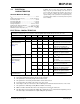
TEMPERATURE CHARACTERISTICS
Bus Free Time
(Note 5)
T
BUF
4700 — — ns Standard Mode
1300 — — ns Fast Mode
— — — ns High Speed Mode 1.7
— — — ns High Speed Mode 3.4
Input Filter
Spike Suppression
(SDA and SCL)
(Not Tested)
T
SP
— — — ns Standard Mode
(Not Applicable)
— 50 — ns Fast Mode
— 10 — ns High Speed Mode 1.7
— 10 — ns High Speed Mode 3.4
Electrical Specifications: Unless otherwise indicated, V
DD
= +2.7V to +5.5V, V
SS
= GND.
Parameters Symbol Min Typical Max Units Conditions
Temperature Ranges
Specified Temperature Range T
A
-40 — +125 °C
Operating Temperature Range T
A
-40 — +125 °C
Storage Temperature Range T
A
-65 — +150 °C
Thermal Package Resistances
Thermal Resistance, 10L-MSOP θ
JA
—202—°C/W
I
2
C SERIAL TIMING SPECIFICATIONS (CONTINUED)
Electrical Specifications: Unless otherwise specified, all limits are specified for T
A
= -40 to +125°C, V
SS
= 0V,
Standard and Fast Mode: V
DD
= +2.7V to +5.5V
High Speed Mode: V
DD
= +4.5V to +5.5V.
Parameters Sym Min Typ Max Units Conditions
Note 1:
This parameter is ensured by characterization and is not 100% tested.
2: After a Repeated Start condition or an Acknowledge bit.
3: If this parameter is too short, it can create an unintentional Start or Stop condition to other devices on the I
2
C bus line. If
this parameter is too long, the Data Input Setup (T
SU:DAT
) or Clock Low time (T
LOW
) can be affected.
Data Input: This parameter must be longer than t
SP
.
Data Output: This parameter is characterized, and tested indirectly by testing T
AA
parameter.
4: This specification is not a part of the I
2
C specification. This specification is equivalent to the Data Hold Time (T
HD:DAT
)
plus SDA Fall (or rise) time: T
AA
= T
HD:DAT
+ T
FSDA
(OR T
RSDA
).
5: Time between Start and Stop conditions.