MCP4725 SOT-23-6 Evaluation Board User’s Guide © 2007 Microchip Technology Inc.
Note the following details of the code protection feature on Microchip devices: • Microchip products meet the specification contained in their particular Microchip Data Sheet. • Microchip believes that its family of products is one of the most secure families of its kind on the market today, when used in the intended manner and under normal conditions. • There are dishonest and possibly illegal methods used to breach the code protection feature.
MCP4725 SOT-23-6 EVALUATION BOARD USER’S GUIDE Table of Contents Preface ........................................................................................................................... 1 Introduction............................................................................................................ 1 Document Layout .................................................................................................. 1 Conventions Used in this Guide ..........................................
MCP4725 SOT-23-6 Evaluation Board User’s Guide NOTES: DS51669A-page iv © 2007 Microchip Technology Inc.
MCP4725 SOT-23-6 EVALUATION BOARD USER’S GUIDE Preface NOTICE TO CUSTOMERS All documentation becomes dated, and this manual is no exception. Microchip tools and documentation are constantly evolving to meet customer needs, so some actual dialogs and/or tool descriptions may differ from those in this document. Please refer to our web site (www.microchip.com) to obtain the latest documentation available. Documents are identified with a “DS” number.
MCP4725 SOT-23-6 Evaluation Board User’s Guide CONVENTIONS USED IN THIS GUIDE This manual uses the following documentation conventions: DOCUMENTATION CONVENTIONS Description Arial font: Italic characters Represents Referenced books Emphasized text A window A dialog A menu selection A field name in a window or dialog A menu path MPLAB® IDE User’s Guide ...is the only compiler...
Preface RECOMMENDED READING This user's guide describes how to use MCP4725 SOT-23-6 Evaluation Board. The following Microchip documents are available and recommended as supplemental reference resources. PICkit™ Serial Analyzer User’s Guide (DS51647) Consult this document for instructions on how to use the PICkit Serial Analyzer hardware and software. MCP4725 Data Sheet, “12-Bit DAC with EEPROM Memory in SOT-23-6” (DS22039) This data sheet provides detailed information regarding the MCP4725 product family.
MCP4725 SOT-23-6 Evaluation Board User’s Guide DOCUMENT REVISION HISTORY Revision A (October 2007) • Initial Release of this Document. DS51669A-page 4 © 2007 Microchip Technology Inc.
MCP4725 SOT-23-6 EVALUATION BOARD USER’S GUIDE Chapter 1. Quick Start Instructions 1.1 INTRODUCTION The following sections provide an overview of the MCP4725 SOT-23-6 Evaluation Board and Instruction how to program the DAC register and EEPROM of the MCP4725 device using the PICkit Serial Analyzer. The following sections cover the following topics: • What is the MCP4725 SOT-23-6 Evaluation Board? • How to use the MCP4725 SOT-23-6 Evaluation Board with the PICkit Serial Analyzer 1.
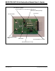
MCP4725 SOT-23-6 Evaluation Board User’s Guide JP1: A0 selection jumper: Picture shown here is connected to the GND (A0 = 0) MCP4725 in SOT-23-6 package J1 Connector Ground Terminal Analog Output Terminal (VOUT) VDD Terminal R1 (Pull-up Resistor for SDA) R3 (Pull-up Resistor for SCL) FIGURE 1-1: DS51669A-page 6 MCP4725 SOT-23-6 Evaluation Board. © 2007 Microchip Technology Inc.
Quick Start Instructions 1.3.1 Getting Started with PICkit Serial Analyzer This section describes how to evaluate the MCP4725 device using the PICkit Serial Analyzer. 1.3.1.1 HARDWARE SET-UP 1. Connect the MCP4725 SOT-23-6 Evaluation Board and the PICkit Serial Analyzer together using the J1 connector. 2. Connect a USB cable between the PICkit Serial Analyzer and a Personal Computer. 3. Connect a Digital Voltmeter to VOUT and GND terminals on the MCP4725 SOT-23-6 Evaluation Board.
MCP4725 SOT-23-6 Evaluation Board User’s Guide 1.3.1.2 PICKIT SERIAL ANALYZER PC SOFTWARE SET-UP FOR DAC DEVICE PROGRAMMING AND ANALOG VOLTAGE OUTPUT MEASUREMENT 1. Install the PICkit Serial Analyzer software in your computer. 2. Connect the USB cable between the PICkit Serial Analyzer and your PC. 3. Run the PICkit Serial PC Software: It will open up the following graphic user interface (GUI). Click Next > and follow the instructions: 4.
Quick Start Instructions 5. Select either 100 kHz option or 400 kHz option radio button and click the Next > button. Note: The MCP4725 SOT-23-6 Evaluation Board supports the I2C bus data rate up to 3.4 MHz, but the current version of the PICkit Serial Analyzer only supports the I2C bus data rate up to 400 kHz. 6. Select No on Device Pullups and click the Next > button. Note: The MCP4725 SOT-23-6 Evaluation Board has its own pull-up resistors © 2007 Microchip Technology Inc.
MCP4725 SOT-23-6 Evaluation Board User’s Guide 7. Select the Voltage Source option for the MCP4725 SOT-23-6 Evaluation Board and click the Next > button. Case 1: When you use VDD from the PICkit Serial Analyzer: If you choose PICkit Serial will power my device option, and the 5 Volt option as shown below, the MCP4725 SOT-23-6 Evaluation Board is powered by the 5 VDC from the PICkit Serial Analyzer through the J1 connector.
Quick Start Instructions 8. Click the OK button. You have done all PICkit Serial Analyzer Configuration Set-up. You are now ready to program the MCP4725 device using the PICkit Serial Analyzer. © 2007 Microchip Technology Inc.
MCP4725 SOT-23-6 Evaluation Board User’s Guide 1.3.2 Creating Script File to program the DAC Register and EEPROM Data 1. From the Communications tab, select the Script option and go to the Script Builder. DS51669A-page 12 © 2007 Microchip Technology Inc.
Quick Start Instructions 2. You need to create a script file using the following instructions. a) Type in any script name (i.e., MCP4725_Write) in the space below the Script Name menu item. b) Type in the following parameters in order in the text box area provided in the Script Detail box.
MCP4725 SOT-23-6 Evaluation Board User’s Guide 3. Programming DAC Register (Fast Mode) a) Change 2nd and 3rd data bytes you want in the Script Detail. b) Click Execute Script Menu item. c) The device gives an analog output voltage (VOUT) at the VOUT terminal on the board. DS51669A-page 14 © 2007 Microchip Technology Inc.
Quick Start Instructions 4. Programming DAC Register and EEPROM a) Type in the following parameters in order in the spaces below the Script Detail menu and click on the Execute Script button.
MCP4725 SOT-23-6 Evaluation Board User’s Guide 5. Verifying the EEPROM Data. After sending the EEPROM write command in Step 4, the device holds the data in the EEPROM. The data in the EEPROM is non-volatile. To check this non-volatile data, you can remove the VDD from the MCP4725 SOT-23-6 Evaluation Board once, and bring back up the VDD again. You will see the same analog voltage output at the VOUT terminal. DS51669A-page 16 © 2007 Microchip Technology Inc.
Quick Start Instructions 6. Reading the DAC Register Data using the PICkit Serial Analyzer This experiment can be done in two steps: (a) Write the DAC Register with Fast Mode Command. (b) Send Read Command and see the results on the PICkit Serial Transactions page. Requesting 3 Bytes Written Data using a Write Command Reading Data using a Read Command © 2007 Microchip Technology Inc.
MCP4725 SOT-23-6 Evaluation Board User’s Guide 7. Reading both the DAC Register and EEPROM data. This experiment can be done by two steps: (a) Write the DAC Register and EEPROM data using a write command. (b) Send Read Command (Request 5 bytes) and see the results on the PICkit Serial Transactions page. Requesting 5 Bytes Written Data using a Write Command DAC Register Data EEPROM Data Reading Data using a Read Command DS51669A-page 18 © 2007 Microchip Technology Inc.
Quick Start Instructions 1.3.3 Examples of the MCP4725 Programming 1 1 0 0 A2 Device Code A1 A0 R/W Address Byte * * Address Byte: A2 = A1 = 0 for Default Samples A0 = 0 if A0 pin is Grounded = 1 if A0 pin is tied to VDD EXAMPLE: Write Mode: 0XC0 FOR (A2 = A1 = A0) 0XC2 FOR (A2 = A1 = 0, A0 = TIED TO VDD) Read Mode: 0XC1 FOR (A2 = A1 = A0) 0XC3 FOR (A2 = A1 = 0, A0 = TIED TO VDD) FIGURE 1-3: MCP4725 Device Address Byte. 11 V REF × D N 5V × 2 - = 2.
MCP4725 SOT-23-6 Evaluation Board User’s Guide 11 V REF × D N × 2 - = 2.5V - = 5V -------------------DAC Output = ------------------------4096 4096 Start 0xC0 ACK 0 1 When A2 = A1 = A0 = 0 1 X X PD1 PD0 X ACK D11 D10 D9 D8 D7 D6 D5 D4 ACK 0x08 = 211 0x60 D3 D2 D1 D0 x x x x ACK STOP 0x00 FIGURE 1-5: VREF = 5V. DS51669A-page 20 Write Command Example for EEPROM and DAC Register for VOUT = 2.5V when © 2007 Microchip Technology Inc.
MCP4725 SOT-23-6 EVALUATION BOARD USER’S GUIDE Appendix A. Schematics and Board Layouts A.1 INTRODUCTION This appendix contains the following schematics and layouts for the MCP4725 SOT-23-6 Evaluation Board: • • • • Board – Schematic Board – Top Layer Board – Top Silk Layer Board – Bottom Metal Layer © 2007 Microchip Technology Inc.
MCP4725 SOT-23-6 Evaluation Board User’s Guide A.2 BOARD - SCHEMATIC DS51669A-page 22 © 2007 Microchip Technology Inc.
Schematics and Board Layouts A.3 BOARD - TOP LAYER © 2007 Microchip Technology Inc.
MCP4725 SOT-23-6 Evaluation Board User’s Guide A.4 BOARD - TOP SILK LAYER DS51669A-page 24 © 2007 Microchip Technology Inc.
Schematics and Board Layouts A.5 BOARD - BOTTOM LAYER © 2007 Microchip Technology Inc.
MCP4725 SOT-23-6 Evaluation Board User’s Guide NOTES: DS51669A-page 26 © 2007 Microchip Technology Inc.
MCP4725 SOT-23-6 EVALUATION BOARD USER’S GUIDE Appendix B. Bill Of Materials (BOM) TABLE B-1: Qty BILL OF MATERIALS (BOM) Reference Description Manufacturer Part Number 2 C1, C2 Not Populated — — 3 GND, VDD VOUT TEST POINT PC COMPACT SMT Keystone Electronics 5016 1 J1 CONN HEADER 6POS .100 R/A GOLD Molex/Waldom Electronics Corp 22-28-8062 2 JP1,JP2 CONN HEADER 2POS .
WORLDWIDE SALES AND SERVICE AMERICAS ASIA/PACIFIC ASIA/PACIFIC EUROPE Corporate Office 2355 West Chandler Blvd. Chandler, AZ 85224-6199 Tel: 480-792-7200 Fax: 480-792-7277 Technical Support: http://support.microchip.com Web Address: www.microchip.