
User manual


MCP46XXEV Evaluation Board User’s Guide
DS51929A-page 30 © 2010 Microchip Technology Inc.
2.6 MCP4661 DEMO STEPS
This demo assumes that you know how to configure the PICkit Serial Analyzer for
Master I
2
C operation. See Section 2.5 “Configuring The PICkit™ Serial Analyzer”
or the “PICkit Serial Analyzer User’s Guide” (DS51647) for additional information.
1. Plug the PICkit serial device into the PC’s USB port.
2. Plug the MCP46XXEV Evaluation Board into the PICkit serial.
3. Add the User Scripts (see Example 2-1) to the CommScripts.TXT file.
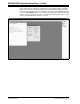
4. Start the PICkit serial GUI.
5. Ensure the GUI is in Master I
2
C communication mode (see Figure 2-7).
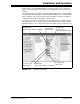
6. Ensure that the Master I
2
C configuration is appropriately configured (see
Figure 2-9).
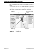
7. Measure the Wiper 0 voltage on the MCP46XXEV Evaluation Board (see
Figure 2-2) using an oscilloscope or digital multimeter. Measure voltage from the
ground plane (GND) to the wiper (P12). The voltage on the wiper should be ~
V
DD
/2 (~2.5V).
8. Open the Script Builder window (see Figure 2-11).
9. Double click on the “MCP4661W0WR” script in the “Example I2CM Scripts
column. This loads the Script Detail column (see Figure 2-13).
10. Click on the Execute Script button. This executes the script shown in the Script
Detail column, which will update the wiper value to 7Fh. The wiper voltage will
now be ~V
DD
/2 (~2.5V).
11. Select the “MCP4661W0RD” script in the User I2CM Scripts column. It should
look like Figure 2-14.
12. Click on the Execute Script button. This executes the script shown in the Script
Detail column. The Transaction window (see Figure 2-17) will be updated to
indicate the execution of the script.
13. Double click on the “MCP4661W0WR” script in the Example I2CM Scripts
column. This loads the Script Detail column (see Figure 2-13). Modify the fourth
byte to FF (see Figure 2-15).
14. Click on the Execute Script button. This executes the script shown in the Script
Detail column, which will update the wiper value to FFh. The wiper voltage will
now be ~V
DD
(~5.0V).
15. Select the “MCP4661W0RD” script in the User I2CM Scripts column. It should
look like Figure 2-14.
16. Click on the Execute Script button. This executes the script shown in the Script
Detail column. The Transaction window (see Figure 2-17) will be updated to
indicate the execution of the script.
17. Double click on the “MCP4661W0WR” script in the Example I2CM Scripts
column. This loads the Script Detail column (see Figure 2-13). Modify the fourth
byte to 3F (see Figure 2-15).
18. Click on the Execute Script button. This executes the script shown in the Script
Detail column, which will update the wiper value to 3Fh. The wiper voltage will
now be ~V
DD
/4 (~1.25V).
19. Select the “MCP4661W0RD” script in the User I2CM Scripts column. It should
look like Figure 2-14.
20. Click on the Execute Script button. This executes the script shown in the Script
Detail column. The Transaction window (see Figure 2-17) will be updated to
indicate the execution of the script.
21. In the Transaction window, click the Clear button.