
User manual


Installation and Operation
© 2010 Microchip Technology Inc. DS51929A-page 13
2.3 GETTING STARTED
The MCP46XXEV Evaluation Board allows quick evaluation of the MCP4661-103E/ST
device. The understanding of the device characteristics (such as the resistor network)
is applicable to any of the devices in the MCP46XX family. The MCP4661-103 device
has a typically R
AB
resistance of 10 kΩ. Evaluation can be done by:
• Using the PICkit Serial Analyzer for interface communication
• Jumpering the MCP46XXEV Evaluation Board into your application circuit to
control the MCP4661-103 device
This user guide will discuss the steps needed to evaluate the MCP4661-103E/ST
device using the PICkit Serial Analyzer (order number: DV164122).
Section 2.5 “Configuring The PICkit™ Serial Analyzer” shows the steps to
configure the PICkit Serial Analyzer as well as create User Script files which are used
to communicate with the MCP4661, based on the devices SPI communication protocol
format.
2.4 MCP46XXEV EVALUATION BOARD DESCRIPTION
The MCP46XXEV Evaluation Board uses the flexible TSSOP20EV Evaluation Board
PCB. This simple evaluation board allows the system designer to quickly evaluate the
operation of the MCP4661-103 device (R
AB(TYP)
= 10 kΩ) using the PICkit Serial
Analyzer or by jumpering the board into their application system. The PICkit Serial
Analyzer is available separately (order number: DV164122).
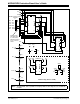
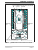
2.4.1 The Hardware
Figure 2-2 shows the component layout of the MCP46XXEV Evaluation Board. This is
a small four-layer board (3.9" x 2.1" (99.06 mm x 53.34 mm)). There are twenty-two
connection points/pads that can use either through-hole or surface-mount connector
posts.
The pad labeled V
DD
is connected to the PCB power plane, while the pad labeled V
SS
is connected to the PCB ground plane. All the passive components that are connected
to V
DD
or V
SS
are connected to either the power plane or ground plane.
The twenty remaining PCB pads correspond to the device pins (i.e.; pad 1 connects to
pin 1).
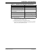
Each pad has two passive components associated with them: a pull-up resistor and a
pull-down resistor. The pull-up resistor is always RXU and the pull-down resistor is
RXD. The “X” is a numeric value that corresponds to a particular pad (1 to 8). As an
example, Pad 5’s pull-up resistor is R5U. Capacitor C1 and C2 are the power supply
filtering capacitors. For whichever pin is the device’s V
DD
, the RxD component footprint
can be used for the device’s bypass capacitor. Table 2-2 describes the components.
A 6-pin header interface is available to support the PICkit Serial or the PIC
®
MCU
In-Circuit Serial Programming™ (ICSP™) interface.
The MCP4661 is bottom aligned in the U3 footprint so that the interface signals are on
the same U3 package pins as future device. This is planned to be similar to the footprint
compatibility between the MCP42X1 and MCP43X1 devices.