
Datasheet


MCP454X/456X/464X/466X
DS22107B-page 72 2008-2013 Microchip Technology Inc.
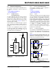
Figure 8-8 shows possible layout implementations for
an application to support the quad and dual options on
the same PCB.
FIGURE 8-8: Layout to Support Quad and
Dual Devices.
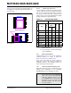
8.5.2.3 PCB Area Requirements
In some applications, PCB area is a criteria for device
selection. Table 8-2 shows the package dimensions
and area for the different package options. The table
also shows the relative area factor compared to the
smallest area. For space critical applications, the QFN
package would be the suggested package.
TABLE 8-2: PACKAGE FOOTPRINT
(1)
8.5.3 RESISTOR TEMPCO
Characterization curves of the resistor temperature
coefficient (Tempco) are shown in Figure 2-10,
Figure 2-21, Figure 2-32, and Figure 2-43.
These curves show that the resistor network is
designed to correct for the change in resistance as
temperature increases. This technique reduces the
end-to-end change in R
AB
resistance.
8.5.4 HIGH VOLTAGE TOLERANT PINS
High Voltage support (V
IHH
) on the Serial Interface pins
supports user configuration of the Nonvolatile
EEPROM, Write Protect, and WiperLock feature.
Potentiometers Devices
Rheostat Devices
MCP44X1
MCP46X1
MCP44X2
MCP46X2
Package Package Footprint
Pins
Type
Code
Dimensions
(mm)
Area (mm
2
)
Relative Area
XY
8
MSOP MS 3.00 4.90 14.70 1.63
DFN (3x3) MF 3.00 3.00 9.00 1
10
MSOP UN 3.00 4.90 14.70 1.63
DFN (3x3) MF 3.00 3.00 9.00 1
14 TSSOP ST 5.10 6.40 32.64 3.62
QFN (4x4) ML 4.00 4.00 16.00 1.78
16
TSSOP
(2)
ST 6.60 6.40 42.24 3.63
QFN (4x4)
(2)
ML 4.00 4.00 16.00 1.78
Note 1: Does not include recommended land
pattern dimensions.
2: These packages are for the Quad output
devices (MCP44x1).
Note: In many applications, the High Voltage will
only be present at the manufacturing
stage so as to “lock” the Nonvolatile wiper
value (after calibration) and the contents
of the EEPROM. This ensures that since
High Voltage is not present under normal
operating conditions, that these values
can not be modified.